IFM OT5212 Handleiding
IFM
Niet gecategoriseerd
OT5212
Bekijk gratis de handleiding van IFM OT5212 (2 pagina’s), behorend tot de categorie Niet gecategoriseerd. Deze gids werd als nuttig beoordeeld door 17 mensen en kreeg gemiddeld 4.9 sterren uit 9 reviews. Heb je een vraag over IFM OT5212 of wil je andere gebruikers van dit product iets vragen? Stel een vraag
Pagina 1/2

Sachnr. 701897/00 12/04
R
Montageanleitung
Installation Instructions
Notice de Montage
Reflexlichttaster mit
Hintergrundausblendung
OTH
Diffuse-reflection sensor
withbackground
suppression OTH
Système réflexion directe
avec suppression de
l’arrière-plan OTH
Bestimmungsgemäße Verwendung
Der Reflexlichttaster erfaßt berührungslos Gegenstände und Materialien
und meldet sie durch ein Schaltsignal.
Tastweite (“range”) siehe Typaufkleber.
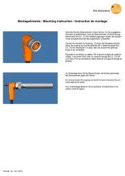
Montage
Richten Sie den Reflexlichttaster auf das zu erfassende Objekt aus und
montieren Sie ihn mit Hilfe einer Montagehalterung.
Die zu erfassenden Objekte sollten sich quer zur Geräteoptik bewegen.
Bei anderen Bewegungsrichtungen sollte vorher getestet werden, ob
eine sichere Funktion gewährleistet ist.
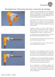
Elektrischer Anschluß
Schalten Sie die Anlage spannungsfrei. Schließen Sie das Gerät
nach den Angaben auf dem Typenschild an.
Adernfarben bei Kabelgeräten: BN = braun, BK = schwarz,
WH = weiß, BU = blau.
Justieren
Führen Sie folgende Schritte durch:
1. Stellen Sie das Poti auf die kleinste Tastweite ein.
2. Plazieren Sie das zu erfassende Objekt im Erfassungsbereich.
3. Erhöhen Sie die Tastweite, bis die gelbe LED aufleuchtet
(= Minimalwert; Objekt erkannt).
4. Entfernen Sie das Objekt aus dem Tastbereich (gelbe LED verlischt).
5. Erhöhen Sie die Tastweite, bis die gelbe LED aufleuchtet
(= Maximalwert; Hintergrund erkannt).
6. Stelle Sie die Tastweite auf die Mittelstellung zwischen Minimal-
wert und Maximalwert.
Betrieb
Prüfen Sie, ob das Gerät sicher funktioniert.
•Die grüne LED leuchtet bei Betriebsbereitschaft.
•Die gelbe LED leuchtet bei Lichtempfang (= Objekt erkannt).
Sie blinkt bei Verschlechterung des Empfangs (z. B. durch Verschmut-
Wartung: Halten Sie die Linsen des Geräts von Verschmutzung frei.
•
zung der Linsen oder durch Dejustage).
Einstellpotentiometer
LED gelb
LED grün
Tastweite

Functions and features
The diffuse-reflection sensor detects objects and materials without
contact and indicates their presence by a switched signal.
Range: see type label.
Installation
Align the photocell and fasten to a mounting device.
The objects to be detected are to move tranversally to the lens of the
unit. In case of other directions of movement it should be tested before
whether safe functioning is guaranteed.
Electrical connection
Isolate power, then connect the unit (see type label).
Core colours (for units with cable connection): BN = brown,
BK = black, WH = white, BU = blue.
Adjustment
Proceed as follows:
1. Set the potentiometer to the smallest sensing range
2. Place the object to be detected within the sensing range
3. Increase the sensing range until the yellow LED lights
(= minimum value; object detected)
4. Remove the object from the sensing range (yellow LED goes off)
5. Increase the sensing range until the yellow LED lights
(= maximum value; background detected)
6. Set the sensing range to the medium position between minimum
and maximum value
Operation
Check the safe functioning of the diffuse-reflection sensor.
•The green LED lights when the unit is ready for operation.
•The yellow LED flashes if reception deteriorates (e.g. by soiled
lenses or by maladjustment).
Maintenance: Keep the lenses of the sensor free from soiling.
Fonctionnement et caractéristiques
Le système réflexion directe détecte des objets et matières sans contact
et indique leur présence par un signal de commutation.
Portée: voir l’étiquette.
Montage
Orienter le système réflexion directe en direction de l’objet à détecter et
le fixer avec une équerre de fixation.
Le mouvement des objets à détecter doit être transversal par rapport à
la lentille de la cellule. En cas d’autres directions de mouvement on
devrait préalablement vérifier le bon fonctionnement.
Raccordement électrique
Mettre l’installation hors tension avant le raccordement de la
cellule optoélectronique.
Raccordement selon les indications de l’étiquette.
Couleurs des fils (pour les cellules avec raccordement par câble):
BN = brun, BK = noir, WH = blanc, BU = bleu.
Réglage
Procéder comme suit:
1. Régler le potentiomètre à la portée minimum
2. Poser l’objet à détecter dans la zone de détection
3. Augmenter la portée jusqu’à ce que la LED jaune brille
(= valeur minimum, objet détecté)
4. Enlever l’objet de la zone de détection (LED jaune s’éteint)
5. Augmenter la portée jusqu’à ce que la LED jaune brille
(= valeur maximum, arrière-plan détecté)
6. Réglage de la portée à une position moyenne entre les valeurs
minimum et maximum
Fonctionnement
Vérifier le bon fonctionnement de la cellule. Indication par LED.
•La LED verte est allumée si l’appareil est disponible.
•
(= objet détecté).
sur les lentilles ou mauvais alignement).
Entretien: Les lentilles de la cellule doivent être dégagées de tout
encrassement.
potentiomètre de réglage
LED jaune
LED verte
portée
setting potentiometer
Yellow LED
Green LED
sensing range
•The yellow LED lights if light is received (= object detected).
•La LED jaune est allumée en cas de réception de lumière
La LED jaune clignote si la réception se détériore (p.ex. salissures
Product specificaties
| Merk: | IFM |
| Categorie: | Niet gecategoriseerd |
| Model: | OT5212 |
Heb je hulp nodig?
Als je hulp nodig hebt met IFM OT5212 stel dan hieronder een vraag en andere gebruikers zullen je antwoorden
Handleiding Niet gecategoriseerd IFM
3 September 2025
3 September 2025
2 September 2025
27 Augustus 2025

15 Augustus 2025
15 Augustus 2025

15 Augustus 2025
15 Augustus 2025
15 Augustus 2025

14 Augustus 2025
Handleiding Niet gecategoriseerd
- Vertiv
- Kontakt Chemie
- Gaggia
- Dual
- Cable Matters
- Car Jack
- EVE
- KNEKT
- Samsung
- Plus More
- XCell
- Rockustics
- TCW Technologies
- WilTec
- G.Skill
Nieuwste handleidingen voor Niet gecategoriseerd

14 September 2025

14 September 2025

13 September 2025

13 September 2025

13 September 2025

13 September 2025

13 September 2025

13 September 2025

13 September 2025

13 September 2025