IFM OC5210 Handleiding
IFM
Niet gecategoriseerd
OC5210
Bekijk gratis de handleiding van IFM OC5210 (2 pagina’s), behorend tot de categorie Niet gecategoriseerd. Deze gids werd als nuttig beoordeeld door 282 mensen en kreeg gemiddeld 4.9 sterren uit 141.5 reviews. Heb je een vraag over IFM OC5210 of wil je andere gebruikers van dit product iets vragen? Stel een vraag
Pagina 1/2

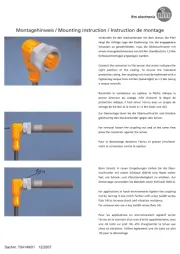
Nach dem elektrischem Anschluß können Sie das Gerät mit Hilfe der
LED-Anzeige genau ausrichten (nur bei OCP..., nicht bei OCPG...):
• LED des Empfängers leuchtet bei genauer Ausrichtung;
• sie blinkt bei ungenauer Ausrichtung.
Maximale Reichweite nur bei genauer Ausrichtung.
Betrieb
Prüfen Sie, ob das Gerät sicher funktioniert.
●Die LED leuchtet bei Lichtempfang (=kein Objekt zwischen Gerät
und Reflektor).
●Die LED blinkt bei Verschlechterung des Empfangs (z. B. durch Ver-
schmutzung der Linsen oder durch Dejustage); (nur bei OCP..., nicht
bei OCPG...).
Wartung
Halten Sie die Linsen des Geräts von Verschmutzung frei.
Verwenden Sie zur Reinigung keine Lösungsmittel oder Reiniger, die
die Kunststofflinsen beschädigen könnten.
range
Bestimmungsgemäße Verwendung
In Verbindung mit Tripelspiegel oder Reflexfolie erfaßt die Reflexlicht-
schranke berührungslos Gegenstände und Materialien und meldet sie
durch ein Schaltsignal.
Standard-Reichweite ("range") OCP...: 5m; OCPG... (Reflexlichtschran-
ke mit kleiner Hysterese): 3m; (Werte bezogen auf Tripelspiegel mit ∅
80mm).
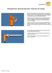
Montage
Befestigen Sie Tripelspiegel oder Reflexfolien. Richten Sie die Reflex-
lichtschranke darauf aus und befestigen Sie sie mit Hilfe einer Monta-
gehalterung.
Elektrischer Anschluß
Schalten Sie die Anlage spannungsfrei. Schließen Sie das Gerät
nach den Angaben auf dem Typenschild an.
Adernfarben: BN = braun, BU = blau, BK = schwarz, WH = weiß.
Programmieren der Ausgangsfunktion bei OCPG... durch Anschlußbe-
legung laut Typenschild.
Montageanleitung
Installation Instructions
Notice de Montage
Reflexlichtschranke
Retro-reflective sensor
Système réflex
OC
R
Einstellpotentiometer
Empfindlichkeit
Sachnr. 701040 / 01 02/2000

Suivant le raccordement électrique l’émetteur peut étre orienté préci-
sement à l’aide de la LED (ne s’applique qu’à la cellule OCP...).
• La LED du récepteur brille en cas d’alignement précis.
• Elle clignote en cas de mauvais alignement.
Portée optimale seulement avec une orientation précise.
Fonctionnement
Vérifier le bon fonctionnement de la cellule.
●La LED brille en cas de réception de lumière (= aucun objet entre la
cellule et le réflecteur).
●La LED clignote si la réception se détériore (p.ex. salissures sur les
lentilles ou mauvais alignement; ne s’applique qu’à la cellule OCP...
ne s’applique pas à la cellule OCPG...).
Entretien
Les lentilles de la cellule doivent être dégagées de tout encrassement.
Pour le nettoyage ne pas utiliser de solvants ou de produits qui pour-
raient abîmer les lentilles en plastique.
range
Functions and features
In conjunction with a prismatic reflector or reflective tape the retro-
reflective sensor detects objects and materials without contact and
indicates their presence by a switched signal.
Standard range: OCP..: 5m; OCPG... (retro-reflective sensor with small
hysteresis): 3m; (values referred to prismatic reflector with ∅ 80mm).
Installation
Place prismatic reflector / reflective tape in desired position. Align the
photocell to a mounting bracket.
Electrical connection
Disconnect power before connecting the sensor.
Connection strictly to the indications on the type label.
Core colours: BN = brown, BU = blue, BK = black, WH = white.
For OCPG... the output function is programmed by connecting the
wires in accordance with the type label.
Fonctionnement et caractéristiques
En liaison avec un réflecteur “nid d’abeille” ou une bande adhésive
réflex ce systéme réflex détecte des objets et matières sans contact et
indique leur présence par un signal de commutation.
Portée standard OCP... 5m; portée standard OCPG... (système réflex à
faible hystérésis): 3m; (valeurs sur un réflecteur “nid d’abeille” ∅
80mm).
Montage
Fixer le réflecteur ou la bande adhésive réflex. Orienter la cellule réflex
et la fixer avec une équerre de fixation.
Raccordement électrique
Mettre l’installation hors tension avant le raccordement de la
cellule optoélectronique.
Raccordement strictement selon les indications de l’étiquette.
Couleurs des fils: BN = brun, BU = bleu, BK = noir, WH = blanc.
Pour la cellule OCPG... la fonction sortie peut être programmée
(NO/NF) en raccordant les fils selon l’étiquette.
Following electrical connection the transmitter can be set exactly by
means of the LED display (only for OCP..., not for OCPG...).
• The LED of the receiver lights if the setting is exact.
• It flashes if setting is inexact.
Maximum range is only possible with precise alignment.
Operation
Check the safe functioning of the sensor.
●The LED lights if light is received (= no object between unit and
reflector).
●The LED flashes if reception deteriorates (e.g. by soiled lenses or by
maladjustment; only for OCP... , not for OCPG...).
Maintenance
Keep the lens of the sensor free from soiling.
For cleaning do not use any solvents or cleaning agents which could
damage the plastic lenses.
range
setting potentiometer
sensitivity
potentiomètre de réglage
sensibilité
Product specificaties
| Merk: | IFM |
| Categorie: | Niet gecategoriseerd |
| Model: | OC5210 |
Heb je hulp nodig?
Als je hulp nodig hebt met IFM OC5210 stel dan hieronder een vraag en andere gebruikers zullen je antwoorden
Handleiding Niet gecategoriseerd IFM

3 September 2025

3 September 2025
2 September 2025

27 Augustus 2025

15 Augustus 2025
15 Augustus 2025

15 Augustus 2025
15 Augustus 2025

15 Augustus 2025

14 Augustus 2025
Handleiding Niet gecategoriseerd
- NComputing
- Rapoo
- General
- Fantech
- ASIWO
- Bruder Mannesmann
- Watson
- Vivolink
- HammerSmith
- Toa
- Kanguru
- Freedor
- Senseca
- Ambrogio
- Tronic
Nieuwste handleidingen voor Niet gecategoriseerd

14 September 2025

14 September 2025

13 September 2025

13 September 2025

13 September 2025

13 September 2025

13 September 2025

13 September 2025

13 September 2025

13 September 2025