IFM KV5001 Handleiding
IFM
Niet gecategoriseerd
KV5001
Bekijk gratis de handleiding van IFM KV5001 (2 pagina’s), behorend tot de categorie Niet gecategoriseerd. Deze gids werd als nuttig beoordeeld door 40 mensen en kreeg gemiddeld 5.0 sterren uit 20.5 reviews. Heb je een vraag over IFM KV5001 of wil je andere gebruikers van dit product iets vragen? Stel een vraag
Pagina 1/2

Bestimmungsgemäße Verwendung
Der Näherungsschalter erfaßt berührungslos
Metalle, nahezu alle Kunststoffe, Glas, Kera-
mik, Holz, Papier, Öle, Fette, Wasser und alle
wasserhaltigen Materialien und meldet sie
durch ein Schaltsignal.
Schaltabstand (Sn) einstellbar von 0 ... 15mm.
Arbeitsbereich 0 ... 12,1 mm (Messung auf
geerdete Metallplatte und Wasser; bei anderen
Materialien kürzer).
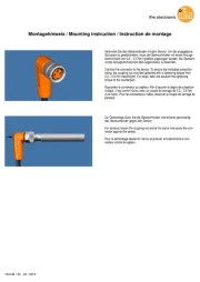
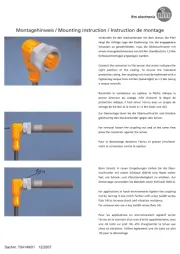
Montage
Befestigen Sie das Gerät sicher auf einer Mon-
tagehalterung. Sichern Sie es bei hoher mecha-
nischer Beanspruchung gegen Loslösen.
Bündig einbaubar (Abb. 1 und 2).
• Freiräume an der aktiven Flächel: Abb. 3.
• Mindestabstände bei Montage mehrerer
Schalter gleichen Typs: Abb. 4 und 5.
Function and features
This proximity switch detects metals, almost all
plastics, glass, ceramics, wood, paper, oils,
greases, water and all hydrous materials with-
out contact and indicates their presence by
providing a switched signal.
Sensing range (Sn) adjustable from 0 ... 15
mm, operating distance 0 ... 12.1 mm;
(measured on an earthed metal plate and
water; a shorter sensing range for other mate-
rials).
Installation
Screw the proximity switch to a firm base. If
there is high mechanical stress, ensure that it
cannot work loose.
Flush mountable (fig. 1 and 2).
• Open space around the sensing face: fig. 3.
• Minimum distance when several switches of
the same type are mounted: fig. 4 and 5.
Fonctionnement et caractéristiques
Ce détecteur de proximité détecte les métaux,
presque tous les pla-stiques, le verre, la céra-
mique, le bois, le papier, les huiles, les graisses,
l’eau et tous les matériaux aqueux sans contact
et indique leur pré-sence par un signal de com-
mutation.
Portée nominale (Sn) réglable de 0 à 15 mm,
portée de travail 0 ... 12,1 mm; (mesurée sur
une plaque mise à la terre ou sur l’eau); en cas
d’autres matériaux portée inférieure à 15 mm).
Montage
Visser le détecteur de proximité sur une base de mon-
tage. En cas de sollicitation mécanique important,
assurer que le détecteur de proximité ne se desserre
pas; encastrable (fig. 1 et 2).
• Zone de dégagement autour de la face active:
fig. 3.
• Distances minimales lorsque plusieurs détecteurs
de la même version sont montés: fig. 4 et 5.
Montageanleitung
Installation Instructions
Notice de Montage
Kapazitiver
Näherungsschalter KVE
Capacitive proximity
switch KVE
Détecteur de proximité
capacitif KVE
Sachnr. 701033/02 02/2006
1
3 x Sn
3
a aa
5
2
8 x Sn
4

Justierung
Verringern des Schaltabstands durch Potentio-
meter (s. Abb. 7):
Erhöhen Sie den Schaltabstand nicht
über Snhinaus!
Betrieb
Prüfen Sie, ob der Schalter sicher funktioniert:
Die LED leuchtet bei durchgeschaltetem Aus-
gang.
Der Betrieb des N herungsschalters ist war-ä
tungsfrei.
Für einwandfreies Funktionieren ist zu beach-
ten:
• äDie aktive Fl che und der Freiraum sollten
von metallischen Ablagerungen und Fremd-
körpern freigehalten werden; insbesondere
bei Montage mit aktiver Fl che nach oben.ä
•EMV: Das Ger t erf llt die Anforderungenä ü
nach EN 60947-5-2.
Adjustment
Decreasing the sensing range by means of a
potentiometer (see fig. 7):
Sensing distance should not ne increased
beyond Sn.
Operation
Check the safe functioning of the switch.
The LED is lit when the output is switched.
The operation of the proximity switch is main-
tenance-free.
For perfect functioning make sure that:
•the sensing face and the open space are
kept free of metal deposits and foreign
bodies, particularly for installation with the
sensing face facing upwards;
•EMC: The unit conforms to the require-
ments of EN 60947-5-2.
Réglage
Réduire la portée à l’ ’ èaide d un potentiom tre
(voir fig. 7):
Ne pas augmenter la prot e au-dessus deé
Sn.
Fonctionnement
Vérifier le bon fonctionnement du détecteur.
La LED est allum e lorsque la sortie est com-é
mut e.é
Cet appareil ne n cessite aucun entretien.é
Pour un bon fonctionnement il faut respecter
les indications suivantes:
• ’ êLa face active et l espace libre doivent tre
d pégagés de toute présence de dé ôts et de
corps étrangers métalliques, notamment en
cas de montage avec la face active vers le
haut.
•CEM: L’appareil est en harmonie avec les exi-
gences selon EN 60947-5-2.
Elektrischer Anschluß
Schalten Sie die Anlage vor dem
Anschluß spannungsfrei!
Öffnen SIe den Sensor (Abb. 6);
schließen Sie die Kabel nach den Anga-
ben auf dem Typenschild an.
Setzen Sie eine Kabelverschraubung ein, um
Schutzart IP67 zu erhalten; sie liegt dem Gerät
nicht bei.
Aktive Fläche ausrichten
Nehmen Sie den Sensorwürfel an (Abb. 7);
richten Sie die aktive Fl che aus und montierenä
Sie den Sensorw rfel wieder.ü
Electrical connection
Disconnect power before connecting the
proximity switch.
Open the switch ( ); connect thefig. 6
cable in accordance with the instructions
on the type lable.
Use cable gland to maintain protection IP67;
cable gland not supplied.
Alignment of the sensing face
Remove the sensor cube ( ); align the sen-fig. 7
sing face and re-insert the sensor cube.
Raccordement électrique
Mettre l’installation hors tension avant le
raccordement du d tecteur de proximité é.
Ouvrir le d tecteur de proximité é (fig. 6);
raccorder le c ble selon les instructionsâ
de l’étiquette.
Il faut utiliser un presse-étoupe pour garantir la
protection IP67 ( commancer sà épar ment).é
Orientation de la face active
Enlever le cube d tecteur ( ); orienter laéfig. 7
face active et remettre le cube détecteur.
6
LED
Potentiometer / Schaltabstand
potentiometer / sensing range
potentiom tre / port eè é
7
1.
Bringen Sie das zu erfassende Material in den
sicheren Schaltbereich.
Schlie erß Öffner
2.
3.
Verringern Sie den
Schaltabstand bis die
LED verlischt.
Verringern Sie den
Schaltabstand bis die
LED aufleuchtet.
Erhöhen Sie den
Schaltabstand bis die
LED aufleuchtet.
Erhöhen Sie den
Schaltabstand bis die
LED verlischt.
1.
Place the target material in the safe
sensing range.
N.O. N.C.
2.
3.
Decrease the
sensing range until
LED goes off.
Decrease the
sensing range until
LED is lit.
Increase the
sensing range until
LED is lit.
Increase the
sensing range until
LED goes off.
1.
Introduire le mat tecteur dans laériau à dé
zone de d tection sé ûre.
N.O. N.F.
2.
3.
Réduire la portée jus-
qu’à ce que la LED
s’éteigne.
Réduire la portée jus-
qu’à ce que la LED
est allumée.
Augmenter la portée
jusqu’à ce que la LED
est allumée.
Augmenter la portée
jusqu’à ce que la LED
s’éteigne.
Product specificaties
| Merk: | IFM |
| Categorie: | Niet gecategoriseerd |
| Model: | KV5001 |
Heb je hulp nodig?
Als je hulp nodig hebt met IFM KV5001 stel dan hieronder een vraag en andere gebruikers zullen je antwoorden
Handleiding Niet gecategoriseerd IFM

3 September 2025

3 September 2025
2 September 2025

27 Augustus 2025

15 Augustus 2025
15 Augustus 2025

15 Augustus 2025
15 Augustus 2025

15 Augustus 2025

14 Augustus 2025
Handleiding Niet gecategoriseerd
- Kunft
- Black Box
- HyperX
- Firefriend
- AXI
- Bravilor
- EWT
- Cayin
- Dream
- Creamsource
- NZR
- Metrel
- Uni-T
- OWC
- Ketron
Nieuwste handleidingen voor Niet gecategoriseerd

14 September 2025

14 September 2025

13 September 2025

13 September 2025

13 September 2025

13 September 2025

13 September 2025

13 September 2025

13 September 2025

13 September 2025