IFM IM5024 Handleiding
IFM
Niet gecategoriseerd
IM5024
Bekijk gratis de handleiding van IFM IM5024 (3 pagina’s), behorend tot de categorie Niet gecategoriseerd. Deze gids werd als nuttig beoordeeld door 29 mensen en kreeg gemiddeld 4.8 sterren uit 15 reviews. Heb je een vraag over IFM IM5024 of wil je andere gebruikers van dit product iets vragen? Stel een vraag
Pagina 1/3

Installation Instructions
Inductive sensor
IME non flush
704288 / 00 09 / 2007
UK
UK
UK
UK
UK

2
Function and features
This sensor detects metals without contact and indicates their presence by provi-
ding a switched signal. The nominal sensing range (Sn) can be seen in the type
designation on the type label on the unit; operating distance (Sa) 0 ... 0,81 x Sn;
(values based on standard measurement with mild steel; a shorter sensing range
for other metals).
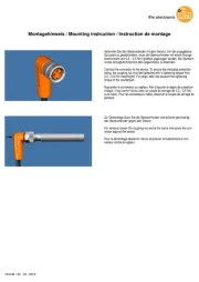
Installation
Screw the proximity switch to a firm
base. If there is high mechanical stress,
ensure that it cannot work loose (fig. 1).
Non-flush installation.
Open space in front of the sensing
face when mounted in metal: fig. 2
and 3.
Minimum distance when several
sensors of the same type are
mounted: fig. 4 and 5.
•
•
9mm
3 x Sna2 x a2 x a
8 x Sn
2 x aa a
2 3
4 5
1

3
UK
Electrical connection
Disconnect power before connecting the sensor. Open the sensor (fig. 6);
connect cable in accordance with the instructions on the type label.
Note: insert a miniature fuse according to the technical data sheet, if specified.
Recommendation: check the unit for reliable function after a short cirucit.
Programming of the output function:
Units which are not programmed by means of connections are provided in N.O.
Open the wire link for programming the N.C. function (fig. 7A).
Aufkle er (B)b
sti ker (B)c
a c auto oll nt (B)
7A
Aufkle er (A)b
sti ker (A)c
a c auto oll nt (A)
Alignment of the sensing face
Remove the sensor cube (fig. 7); align sensing face and re-insert the sensor cube.
When the sensor is mounted on a metal surface, the face of the cube marked by a
sticker (A) must point to this metal surface.
When the sensor has been screwed together, position the marking sticker
provided on the outer surface of the sensor unit so that the sensing face is
marked.
Operation
Check the safe functioning of the sensor: The LED is lit when the supply voltage
is applied.
The operation of the sensor is maintenance free. For perfect functioning make
sure that:
the sensing face and the open space are kept free of metal deposits and
foreign bodies, particularly for installation with the sensing face facing upwards.
EMC: The unit conforms to the requirements of EN 60947-5-2.
•
•
6 7
Product specificaties
| Merk: | IFM |
| Categorie: | Niet gecategoriseerd |
| Model: | IM5024 |
Heb je hulp nodig?
Als je hulp nodig hebt met IFM IM5024 stel dan hieronder een vraag en andere gebruikers zullen je antwoorden
Handleiding Niet gecategoriseerd IFM
3 September 2025
3 September 2025
2 September 2025
27 Augustus 2025

15 Augustus 2025
15 Augustus 2025

15 Augustus 2025

15 Augustus 2025

15 Augustus 2025

14 Augustus 2025
Handleiding Niet gecategoriseerd
- Clean Paper
- Pletscher
- Rival
- The T.mix
- Elbe
- Kimo
- InvisibleShield
- BABY Born
- Vivo
- TELEX
- LINOVISION
- Hähnel
- CRUX
- Deltaco Gaming
- JIMMY
Nieuwste handleidingen voor Niet gecategoriseerd
14 September 2025

14 September 2025

13 September 2025

13 September 2025

13 September 2025

13 September 2025

13 September 2025

13 September 2025

13 September 2025

13 September 2025