IFM AC2752 Handleiding
IFM
Niet gecategoriseerd
AC2752
Bekijk gratis de handleiding van IFM AC2752 (5 pagina’s), behorend tot de categorie Niet gecategoriseerd. Deze gids werd als nuttig beoordeeld door 8 mensen en kreeg gemiddeld 3.7 sterren uit 4.5 reviews. Heb je een vraag over IFM AC2752 of wil je andere gebruikers van dit product iets vragen? Stel een vraag
Pagina 1/5

Operating instructions
AS-i PCB module
AC2750
AC2751
AC2752
AC2753
80285129/00 04/2019
UK

2
1 Preliminary note
An instruction is indicated by "►".
Example: ► Mount the unit as shown.
Important note
Non-compliance can result in malfunction or interference.
2 Safety instructions
• Please read the operating instructions prior to set-up of the device.
• Ensure that the product is suitable for your application without any restrictions.
• The unit conforms to the relevant regulations and EC directives.
• Improper or non-intended use may lead to malfunctions of the unit or to
unwanted effects in your application.
• Installation, electrical connection, set-up, operation and maintenance of the
unit must only be carried out by qualified personnel authorised by the machine
operator.
3 Functions and features
The AS-i module functions as digital I/O slave in the AS-i system and is exclusively
supplied via AS-i. It connects 4 sensors (2-wire sensors or 3-wire sensors) and
max. 4 actuators (pnp) with the AS-i master.
• Maximum number of modules per master: 62 (A/B slave)
• Watchdog function: If the connection to the master is interrupted for more than
40 ms, all outputs are disconnected.
• AS-Interface version 3.0, downward compatible
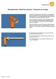
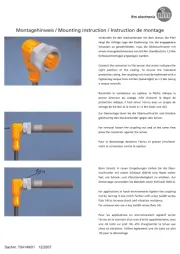
4 Installation
► Disconnect the system from power before installation.
► Install the module in a protected location, e.g. in a housing with at least IP 54.
Use the supplied adhesive pad or the DIN rail adapter E70432 (accessory) for
fixing.
► When using the adhesive pad, the surfaces must be kept free from dust, oil,
release agents and other kinds of contamination.

3
UK
► Position the adhesive pad in the centre of the back of the PCB module.
► Carry out a set-up test after installation of the module.
5 Electrical connection
The unit must be connected by a qualified electrician.
The national and international regulations for the installation of electrical equipment
must be adhered to.
► Disconnect the installation from power and connect the unit.
5.1 External protective circuitry for inductive loads
The switch-on and switch-off capacity for triggering solenoids is rated up to 2.5 W
(IEC 60947-5-1, utilisation category DC-13).
Recommendation: For inductive loads use a free wheel diode on the load.
5.2 Wiring
AC2750 (4 DI / 4 DO) / AC2751 (4 DI / 3 DO)
Connection cables
I1 WH (white)
I2 WH (white)
I3 WH (white)
I4 WH (white)
O1 YE (yellow)
O2 YE (yellow)
O3 YE (yellow)
O4 YE (only AC2750)
0- BK (black)
I+ RD (red)
AS-i - (FLT) BU (blue)
AS-i + (PWR) BN (brown)
Switching input sensor 1
Switching input sensor 2
Switching input sensor 3
Switching input sensor 4
Switching output actuator 1
Switching output actuator 2
Switching output actuator 3
Switching output actuator 4
Sensor and actuator supply 0 V
Sensor and actuator supply 24 V
AS-i -
AS-i +
Product specificaties
| Merk: | IFM |
| Categorie: | Niet gecategoriseerd |
| Model: | AC2752 |
Heb je hulp nodig?
Als je hulp nodig hebt met IFM AC2752 stel dan hieronder een vraag en andere gebruikers zullen je antwoorden
Handleiding Niet gecategoriseerd IFM
3 September 2025
3 September 2025
2 September 2025
27 Augustus 2025

15 Augustus 2025
15 Augustus 2025
15 Augustus 2025
15 Augustus 2025
15 Augustus 2025

14 Augustus 2025
Handleiding Niet gecategoriseerd
- Nikkei
- Kupper
- SecureSafe
- NOCO
- CME
- IOGEAR
- OSD Audio
- Toorx
- Veripart
- Point
- Dresden Elektronik
- Interstuhl
- Ambrogio
- Maico
- Fuji
Nieuwste handleidingen voor Niet gecategoriseerd
14 September 2025

14 September 2025

13 September 2025

13 September 2025

13 September 2025

13 September 2025

13 September 2025

13 September 2025

13 September 2025

13 September 2025