I3International Ax65W Handleiding
Bekijk gratis de handleiding van I3International Ax65W (2 pagina’s), behorend tot de categorie Bewakingscamera. Deze gids werd als nuttig beoordeeld door 49 mensen en kreeg gemiddeld 4.4 sterren uit 25 reviews. Heb je een vraag over I3International Ax65W of wil je andere gebruikers van dit product iets vragen? Stel een vraag
Pagina 1/2
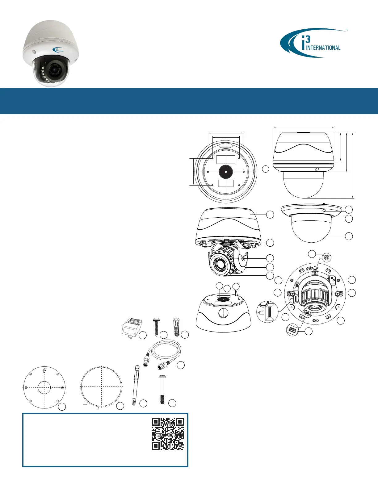
CAMERA PARTS AND DEFINITIONS
3MP Infrared Outdoor IP Dome Camera w/ White Light Ax65W
Thank you for purchasing i3 International’s Annexxus 65W indoor/outdoor 3MP IP dome
camera with built-in white light. Your camera is equipped with a motorized vari-focal
3-10.5mm lens. The lens can be controlled through camera’s Web Interface in Internet
Explorer, through SRX-Pro Server/Remote or through Video Pilot Client. Built-in white light
settings can be congured only through camera’s Web Interface in Internet Explorer.
SAFETY
When installing your Ax65W camera be sure to avoid:
• excessive heat, such as direct sunlight or heating appliances
• contaminants such as dust and smoke
• strong magnetic elds
• moisture and humidity
• areas with mechanical vibrations
• uorescent lamps or objects that reect light and unstable light sources
• temperatures below -40° C (-40° F) and above 50° C (122° F).
POWER
This camera accepts AC24V and PoE+ power. Maximum power consumption: 25W.
Ensure the supplied voltage meets the power consumption requirements of this camera
before powering the camera on. Incorrect voltage may cause irreparable damage to the
video camera and will effectively void the camera warranty.
CLEANING
• For maximum optical clarity, the camera dome or lens must remain clean. Use a soft,
dry cloth to remove nger prints or dust from the dome cover.
• Use a blower to remove dust from the lens.
• Do not use volatile solvents such as alcohol, benzene, or thinners, as they may
damage the surface nish.
SERVICING
To avoid electrical shock and to preserve the product warranty, DO NOT disassemble the
camera. Refer servicing to qualied personnel only.
PACKAGE CONTENTS
Ensure that the items received match those listed on the order form and the packing slip.
In addition to this manual and a fully assembled camera, the dome camera packing box
includes:
A. Standard RJ45 Connector p1-x2
B. Round Head Screw (Tapping Type) w/ O-ring p1-x4
C. Plastic Anchor x4
D. 3ft network cable x1
E. Surface Mount template x1
F. Flush Mount template x1
G. Security torx bit x1
H. Long Machine type screws p1-x3
(for Flush Mounting with back box installations)
i3-TRNG-CAMS-Ax65W-QSG.indd
Rev. 171130
1. Back box. Camera’s back box comes with six (6) 90% pre-drilled hole dimples.
For surface mounting, complete drilling a minimum of two (2) holes.
2. Camera module / second housing.
3. Tilt bracket with locking screw
4. Inner liner / Shroud. Inner liner is attached to the camera module but can be
partially detached for easier lens adjustment.
5. IR board
6. Screws securing the dome bubble housing to camera module (x3, silver)
7. Dome bubble housing / Dome cover
8. Lexan bubble
9. 3/4” waterproof rubber plug. For best waterproof performance, use a network
cable 5mm or more in diameter. To maintain IP67 waterproof rating, use sealant
on the threads during installation. If using the side conduit hole, replace the
rubber plug with the metal plug from the side conduit.
10. 3/4” side conduit hole with metal plug. If using the side conduit hole, remove
the metal plug and use it instead of the rubber plug in the top conduit hole. To
maintain IP67 waterproof rating, use sealant on the threads during installation.
11. Six (6) 90% pre-drilled hole dimples. Complete drilling a minimum of two (2) for
surface mounting.
12. Reset/Default pin-hole button. Press for 1 second to reboot the camera.
Press for 6 seconds to restore camera settings to factory defaults.
13. Micro SD Card slot for on-camera video storage. (microSD card sold separately)
14. Mini USB port. Manufacturer use
only
.
15. Screws attaching camera module to the back box (x3, silver)
16. Screws to engage locking arms (x2, black)
12
13
14
15
16
16
1
2
5
3
4
6
7
8
Scan this QR code or visit ftp.i3international.com to view and
download the full User Manual for this camera. Also available for
download is the AnnexxusConfigurationTool or ACT program
used to locate and congure your cameras with your SRX-Pro
software. This program is already installed in SRX-Pro v3.3.3.69
and higher. Please contact our Technical Support team if you have
any questions or concerns regarding camera installation or you
require software services or support. Technical support can be
reached by email at: support@i3International.com or by
phone toll free 1.877.877.7241.
QR Code to Complete
User Manual / ACT
Lens Direction
GUIDE PATTERN
15
15
GUIDE PATTERN
Cut Line
Camera Outline
A
B
C
D
E
F
G
H
Quick Start Guide
147 mm (5¾”)
68 mm (2.67”)
94 mm (3.7”)
158 mm (6¼”)
63 mm (2.5”)
63 mm (2.5”)
84 mm (3.3”)
9
10
11
9

I/O CONNECTORS
Ax65W IP Dome Camera
QUICK START GUIDE
1.866.840.0004
www.i3international.com
Canada 780 Birchmount Road, Unit 16,
Scarborough, ON, M1K 5H4
1. Use the provided security Torx key to
loosen three silver screws securing
the dome bubble housing to camera
module (#6). Do not completely
remove the screws from the dome
bubble. Set the dome bubble aside.
2. Next, loosen three silver screws
attaching camera to the back box
(#15).
3. Remove camera’s back box and set
aside.
Once the camera’s back box has been removed, the Ax65W input/output connectors will be
revealed on the camera’s module, including RJ45 Ethernet/PoE+ connector, AC24V power
port and Audio/PIR/WLED connectors.
1. Audio Input/Output, PIR Input, Power to external PIR (no more than 2.0W), Power to
external White LED light (no more than 6.8W). Ax65W is compatible with i3 Mo-1
microphones. Note: If no Ext. WLED or PIR is used, Mo-1 microphone can be powered
directly from an otherwise unused WLED 12VDC or PIR 12VDC port.
2. AC 24V Port. Connect AC 24V power supply.
3. RJ45 Ethernet Connector / PoE+. Connect RJ45 network cable for Ethernet/Internet
connectivity. PoE+ (Power over Ethernet+) is supported.
Caution: Do not apply power until the camera is properly and securely mounted.
4. Orange LED. Flashing orange LED indicates data transmission between the camera
and the Internet.
5. Green LED. Solid green LED indicates a current live connection.
DISASSEMBLING THE CAMERA
U.S.A 4450 Witmer Industrial Estates Unit 4
Niagara Falls, NY 14305
FLUSH MOUNTING w/LOCKING ARMS
Note: Based on installation location and surface type, supplied screws and anchors may
not be adequate. This method is suitable for indoor drywall and T-bar installations only.
See complete manual for additional mounting options.
1. Use the Flush Mounting Template to cut a hole
in the mounting surface.
2. Disassemble the camera. Remove camera’s
back box and set aside. It will not be used in
this type of installation.
3. Insert the microSD card into the microSD slot
on the camera module (if using).
4. Insert the camera into the cut hole in the surface.
5. Feed all cables through the opening in the
mounting surface and connect to the camera. Do
not apply power until the installation is complete.
6. Use a Phillips screwdriver to turn two black-colored
screws on the camera module clockwise to engage
the locking arms. Tighten the arms securely
against the mounting surface.
7. Adjust the lens angle by rotating and panning the
camera lens base. Lift off the camera liner for
easy lens position adjustment. Do not over-rotate
the camera lens beyond the stop point to avoid
damage to the camera.
8. Once the desired view is achieved, replace camera liner until it snaps back into place.
9. Replace the camera’s dome bubble on top of the camera module. Use the red dots on
both modules for easy alignment.
10. Use the supplied Torx bit to re-tighten 3 silver screws securing the dome bubble
housing to the camera module.
1
2
3
4 5
Rev. 171130
Audio
In
Power to
Ext. WLED
≤ 6.8W
Au/I
GND
Au/O
WLED
12VDC
PIR/I
PIR
12VDC
GNDGND
CONNECTING CAMERA TO i3 SRX-PRO SERVER
Camera’s default IP address: 192.0.0.16.
Camera’s default Subnet mask address: 255.255.255.0.
Login: i3admin / Password: i3admin
Change your Annexxus camera’s default IP Address:
1. Close SRX-Pro Server software by pressing Alt+Shift+Ctrl+F4.
2. Change the IP address of the onboard NIC (LAN) of your SRX-Pro Server (or
of NIC1 if your SRX-Pro Server has two onboard NIC cards) to 192.0.0.XXX to
match the default IP range of your Annexxus IP camera.
3. Connect your Annexxus camera to i3 SRX-Pro Server (see diagram above).
4. Restart SRX-Pro Server software. Log in and go to the Setup -> IP Camera
tab.
5. Click ACT Config Tool icon. If your NVR does not have
Annexxus Conguration Tool, download and install it from
http://i3international.com/download website.
6. In ANNEXXUS Conguration Tool window, a list of active network cameras will
be displayed. Select your desired camera in the list.
7. Enter the new IP address and Subnet Mask of the camera in the Device(s)
Communication Update area and click Update. The new camera IP address
must match the
original
range of your SRX-Pro LAN or NIC1 card. E.g. If
your original SRX-Pro Server’s IP address was 192.138.10.122, change your
Annexxus camera’s IP address to 192.138.10.XXX.
Remember:
Annexxus Cameras cannot share an IP address, each camera
requires its own unique IP address.
8. Wait a few moments for a “Success” message in the Result eld.
9. Repeat Steps 7-8 for all detected Annexxus cameras in the ACT.
10. Change the IP address of the NIC back to its original setting (reverse Step 2).
Ensure you can connect to your camera using its new IP Address:
11. Open an Internet browser window and enter the new IP Address you have just
assigned to your Annexxus camera in Step 7.
12. Enter the default camera User Name and default Password in the pop-up login
window.
13. Annexxus camera interface will be displayed in the Internet Explorer window.
You should be able to see the camera image on the screen.
If you do not see the camera image on the screen, call i3 International
technical support team for troubleshooting tips: 1.877.877.7241
Add your Annexxus camera to IP Camera tab in SRX-Pro Server:
14. Ensure that the latest version of GiPi updater is installed on your SRX-Pro
Server. Latest GiPi available from http://i3international.com/download
Note:
SRX-Pro must be closed while GiPi updater is installed. After GiPi
updater installation, start i3 SRX-Pro Server software again.
15. Log In and go to the Setup -> IP Camera tab.
16. Click the Search & Add button to display connected Annexxus cameras.
17. Select the detected camera in the list and click Select.
18. In the
Select IP Camera
window, enter the default camera User Name and
Password, then click Add. Selected camera will be added to the IP Camera
list.
19. Assign the IP camera to the SRX-Pro video channel in the Ch In. column.
20. To enable motorized lens’ auto focus feature, go to Hardware tab and select
i3 GiPi from the PTZ Camera Type drop-down menu for the corresponding
channel.
Your Annexxus camera is now connected to SRX-Pro Server and is ready to record.
Change resolution and frame rate for the Annexxus camera in the IP Camera tab
menu or via Web Setup.
i3 SRX-Pro Server
LAN
Via Gigabit Switch
Connection Type 1:
(Camera requires AC power):
Connection Type 2:
i3 SRX-Pro Server
Audio
Out
Power to
PIR
≤ 2.0W
PIR
In
WHITE LED (WLED) LIGHT SETTINGS
Your camera comes equipped with the built-in white LED light, that can be automatically
activated whenever motion or human activity is detected by the camera. Built-in white light
can also be activated in response to the triggered PIR connected to the camera.
External Whilte Light (no more than 6.8W) can be connected directly to the camera and be
activated in response to the same events as the built-in WLED.
See complete manual for instructions.
Product specificaties
| Merk: | I3International |
| Categorie: | Bewakingscamera |
| Model: | Ax65W |
Heb je hulp nodig?
Als je hulp nodig hebt met I3International Ax65W stel dan hieronder een vraag en andere gebruikers zullen je antwoorden
Handleiding Bewakingscamera I3International

13 Maart 2024

13 Maart 2024

13 Maart 2024

13 Maart 2024

13 Maart 2024

13 Maart 2024

13 Maart 2024

13 Maart 2024

13 Maart 2024

13 Maart 2024
Handleiding Bewakingscamera
- Quantum
- Sir Gawain
- Gembird
- Moxa
- Bea-fon
- Marmitek
- Crestron
- Ion
- Bolin Technology
- Caddx
- Braun
- Miniland
- Buffalo
- Schneider
- Qoltec
Nieuwste handleidingen voor Bewakingscamera

15 September 2025
2 September 2025
2 September 2025
2 September 2025
2 September 2025
1 September 2025

1 September 2025
1 September 2025

1 September 2025
1 September 2025