Hozelock Air Pump 320 Handleiding
Bekijk gratis de handleiding van Hozelock Air Pump 320 (78 pagina’s), behorend tot de categorie Pomp. Deze gids werd als nuttig beoordeeld door 32 mensen en kreeg gemiddeld 4.9 sterren uit 6 reviews. Heb je een vraag over Hozelock Air Pump 320 of wil je andere gebruikers van dit product iets vragen? Stel een vraag
Pagina 1/78
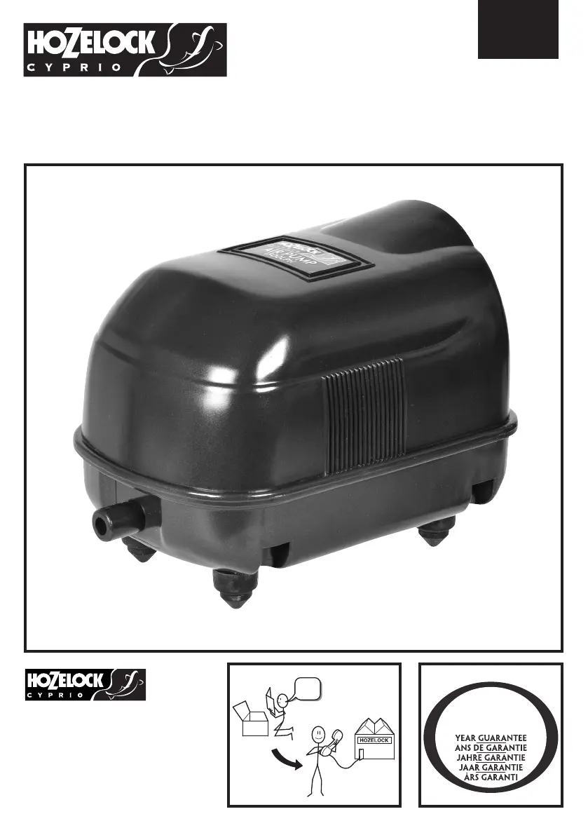
air pump 1500
2823
1810
?
2
Hozelock Ltd.
Midpoint Park,
Birmingham B76 1AB. England
Tel:+44 (0) 121 313 1122
info@hozelock.com
www.hozelock.com
33132-001
Product specificaties
| Merk: | Hozelock |
| Categorie: | Pomp |
| Model: | Air Pump 320 |
Heb je hulp nodig?
Als je hulp nodig hebt met Hozelock Air Pump 320 stel dan hieronder een vraag en andere gebruikers zullen je antwoorden
Handleiding Pomp Hozelock

2 December 2024
26 Juli 2023
7 Juni 2023
13 Mei 2023
10 Mei 2023
15 April 2023
Handleiding Pomp
Nieuwste handleidingen voor Pomp
9 Juli 2026
8 Juli 2026
7 Juli 2026
23 Juni 2026
22 Juni 2026
5 Juni 2026
2 Juni 2026
2 Juni 2026
2 Juni 2026
1 Juni 2026