Hoffman G28 Handleiding
Bekijk gratis de handleiding van Hoffman G28 (40 pagina’s), behorend tot de categorie Heater. Deze gids werd als nuttig beoordeeld door 17 mensen en kreeg gemiddeld 4.3 sterren uit 2 reviews. Heb je een vraag over Hoffman G28 of wil je andere gebruikers van dit product iets vragen? Stel een vraag
Pagina 1/40
© 2017 Pentair Equipment Protection89116684
Rev. C
P/N 89116684
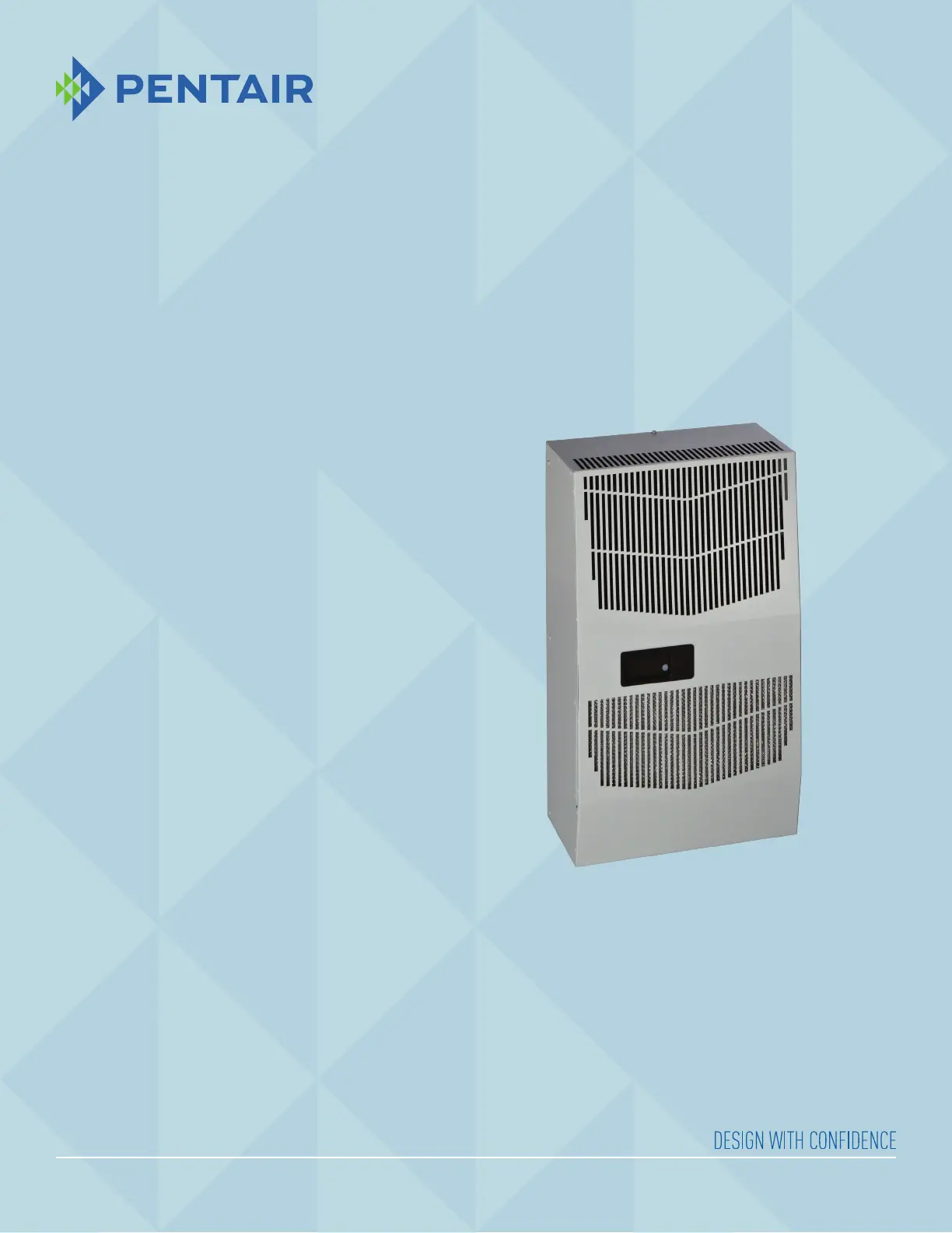
SPECTRACOOL
Air Conditioner
G28 Model
INSTRUCTION MANUAL
Product specificaties
| Merk: | Hoffman |
| Categorie: | Heater |
| Model: | G28 |
| Soort bediening: | Knoppen |
| Kleur van het product: | Grijs |
| Gewicht: | 38101 g |
| Breedte: | 431 mm |
| Diepte: | 256.5 mm |
| Hoogte: | 725 mm |
| Soort: | Ventilator elektrisch verwarmingstoestel |
| Gebruikershandleiding: | Ja |
| Materiaal behuizing: | Kunststof |
| Internationale veiligheidscode (IP): | IP56 |
| Aan/uitschakelaar: | Ja |
| Temperatuur (min): | -8 °C |
| Geschikt voor: | Binnen |
| Instelbare thermostaat: | Ja |
| Temperatuur (max): | 55 °C |
| Draagbaar: | Ja |
| AC-ingangsspanning: | 100-120 V |
| Verwarmingsvermogen: | 1874 W |
| Plaatsingsopties: | Vloer |
| Verwarming power (min): | - W |
| Maximumcapaciteit: | 6400 BTU/h |
Heb je hulp nodig?
Als je hulp nodig hebt met Hoffman G28 stel dan hieronder een vraag en andere gebruikers zullen je antwoorden
Handleiding Heater Hoffman

4 April 2025
4 April 2025
Handleiding Heater
Nieuwste handleidingen voor Heater
1 Juni 2026
1 Juni 2026
28 Mei 2026
27 Mei 2026
27 Mei 2026
27 Mei 2026
26 Mei 2026
26 Mei 2026
25 Mei 2026