Growatt ARK 5.12~25.6XH-A1 Handleiding
Bekijk gratis de handleiding van Growatt ARK 5.12~25.6XH-A1 (2 pagina’s), behorend tot de categorie Accu. Deze gids werd als nuttig beoordeeld door 94 mensen en kreeg gemiddeld 4.5 sterren uit 5 reviews. Heb je een vraag over Growatt ARK 5.12~25.6XH-A1 of wil je andere gebruikers van dit product iets vragen? Stel een vraag
Pagina 1/2
System size
BDC95045-A1
ARK 2.5H-A1
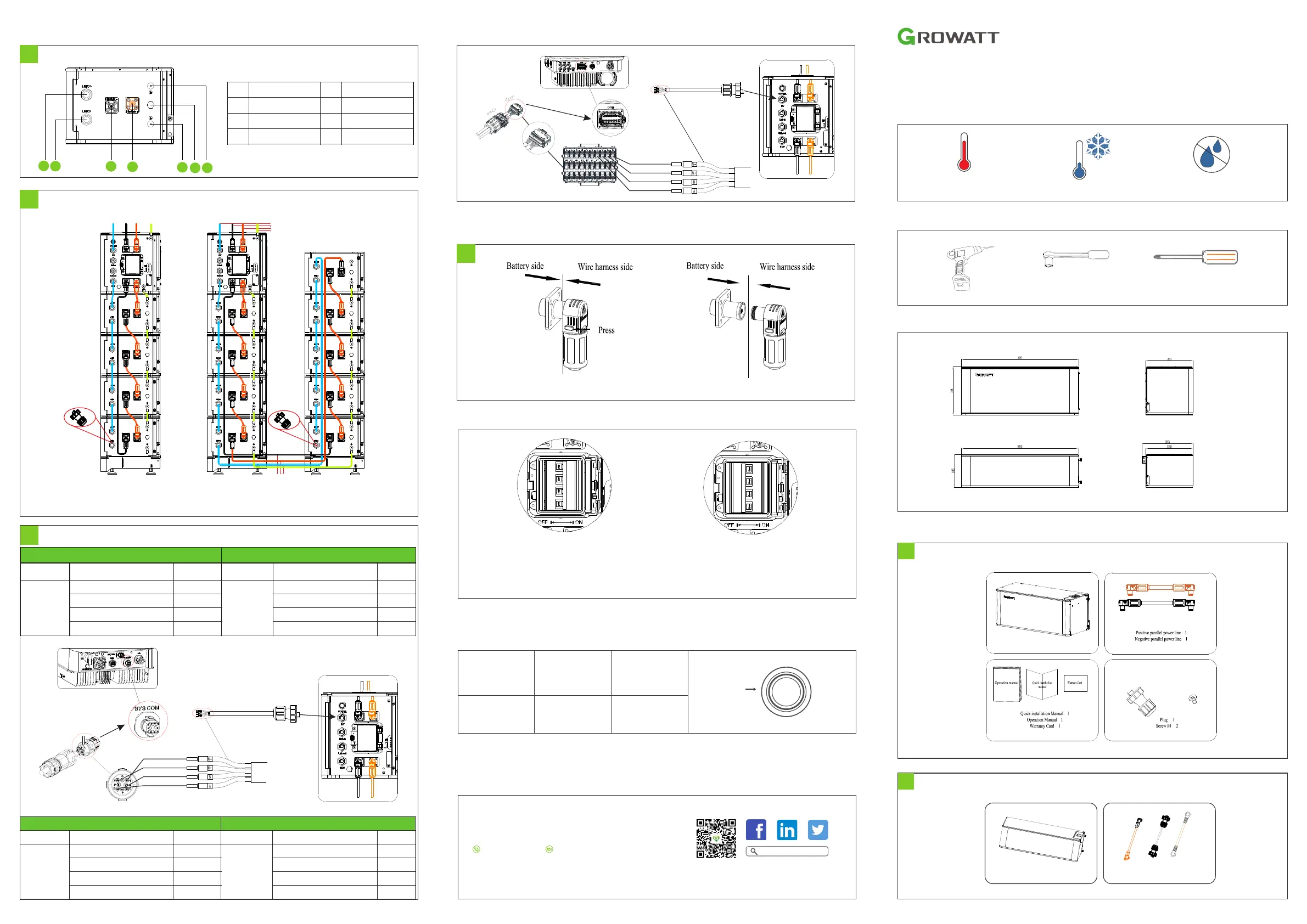
Note:Press the position indicated in the figure above before disconnecting the power terminal.
6.Terminal Connection
Power terminal
6-1
ARK 5.12~25.6XH-A1
Quick Installation Manual
Installation environment
Max.
+50℃
Min.
-10℃
RH.
+5%~+95%
Installation tools
1.Check
Check ARK 2.5H-A1 List
1-2
ARK 2.5H-A11
Serial cable 1
Check BDC 95045-A1 List
1-1
Diagram of wiring connection
5-3
Note:It is not recommended to install a DC circuit breaker between the battery system and the hybird inverter system,
If you want to install a DC circuit breaker with rated working voltage grearer than 1000V and rated working current greater
than 63A, do not operate the DC circuit breaker with power on, otherwise the machine may be damaged.
1
8.Key operation
Power Button
Situation
System of f
Touch
Press(≥5S)
Definition
Power on
Press
Note:When multiple battery syetem are used in parallel connection, you only need to press one key of any module to start the system.
9.Service and contact
Shenzhen Growatt New Energy Co., Ltd
4-13/F,Building A,Sino-German(Europe) Industrial Park,
Hangcheng Ave,Bao’an District, Shenzhen, China
86 0755 2747 1942
service@ginverter.com
W:www.ginverter.com
Growatt New Energy
6
Power ON battery system
Power OFF battery system
7.Battery system switch operation
ARK 2.5H-A1 Connection end face introduction
5-2
1
2
3
4
5
67
To PCS
To PCS
Insert Plug
Insert Plug
ARK 2.5H-A1 Series cable
ARK XH Battery Cable
Battery+
Battery-
Rs485
PE
Rs485
Battery-Battery+PE
1
LINK0 Series
Communication Port
5
GND terminal
2
LINK1 Series
Communication Port
6
Safety vent
3
Module negative
terminal
7
GND terminal
4
Module positive terminal
Power on battery system:
Turn the circuit breaker to the "ON" state, press the
POWER button for 5-6 seconds, wait for the battery
system LED light to light up, indicating that the boot
is complete.
Poweroffbatterysystem:
Turnthebreakerofto"OFF" toturnofftheentirebattery
system.
BDC 95045-A1
Communication line
B
Connector
A
SYS COM “1" to “W-”
SYS COM “2" to “W+”
SYS COM “7" to “B”
SYS COM “8" to “A”
*
*
*
*
*
*
*
*
*
Communication port connection
5-4
5
BDC 95045-A1
MOD TL3-XH
Silk screen
Terminal serial number
Definition
Silk screen
Terminal serial number
Definition
INV
1
WAKE-(W-)
COM
10
BAT.EN-
2
WAKE+(W+)
9
BAT.EN+
7
RS 485_B (B)
8
RS485B2
8
RS 485_A(A)
7
RS485A2
BDC 95045-A1
MIN TL-XH
Silk screen
Terminal serial number
Definition
Silk screen
Terminal serial number
Definition
INV
1
WAKE-(W-)
SYS COM
1
BAT.EN-
2
WAKE+(W+)
2
BAT.EN+
7
RS 485_B (B)
7
RS 485_B
8
RS 485_A(A)
8
RS 485_A
Connector
A
Communication line
B
COM “10" to “W-”
COM “9" to “W+”
COM “8" to “B”
COM “7" to “A”
Product specificaties
| Merk: | Growatt |
| Categorie: | Accu |
| Model: | ARK 5.12~25.6XH-A1 |
Heb je hulp nodig?
Als je hulp nodig hebt met Growatt ARK 5.12~25.6XH-A1 stel dan hieronder een vraag en andere gebruikers zullen je antwoorden
Handleiding Accu Growatt

9 Juli 2023
7 Juli 2023
4 Juli 2023
4 Juli 2023
1 Juli 2023
Handleiding Accu
Nieuwste handleidingen voor Accu
27 Mei 2026
12 Mei 2026
5 Mei 2026
4 Mei 2026
4 Mei 2026
1 Mei 2026
31 Maart 2026
30 Maart 2026
26 Maart 2026
26 Maart 2026