Gossen Metrawatt Metrahit 2+ Handleiding


Lees hieronder de 📖 handleiding in het Nederlandse voor Gossen Metrawatt Metrahit 2+ (18 pagina's) in de categorie Multimeter. Deze handleiding was nuttig voor 26 personen en werd door 2 gebruikers gemiddeld met 4.5 sterren beoordeeld

Pagina 1/18
Operating Instructions
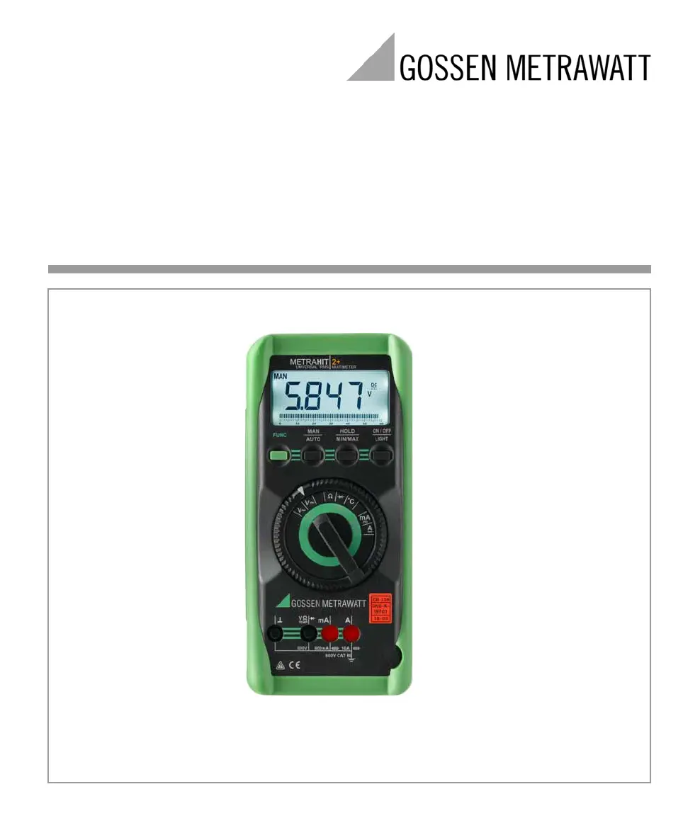
METRAHIT2+
Universal TRMS Multimeter 3-349-476-02
5/10.09
2 GMC-I Messtechnik GmbH
1Display (LCD)
2ON / OFF 
Light
Key for ON / OFF and display illumination
ON / OFF
3HOLD / MIN/MAX Key for the following functions: save
measured value, delete and MIN-MAX
4MAN / AUTO Key for manual measuring range selection
5FUNC Key for selecting ranges or functions
6rotary selector switch for measuring functions
7 Connector jacks
Symbols used in the Digital Display
1 MAN: manual measuring range selection is active
2 MIN/MAX value storage
3 HOLD: display memory, “freeze” measured value
4 Digital display with decimal point and polarity display
5 Diode measurement selected
6 appears when acoustic signal is active
7 Selected type of current
8 Unit of measure
9 Unit of measure  C / F for temperature measurement
10 Triangle appears: indicates overranging
11 Pointer for analog display
12 REL: relative measurement with reference to offset
13 Scale for analog display
14 Indicates that the negative analog display range has been exceeded
15 Warning regarding dangerous voltage: > 40 V AC / 60 DC
16 Display in case of defective fuse
17 Low battery display
18 Symbol for continuous duty
Standard Equipment
1 TRMS digital multimeter
1 Protective rubber holster
2 1.5 V AA size batteries
1 Set of measurement cables KS17-2
1 DKD calibration certificate
1 Short-form operating instructions
1
2
3
4
5
6
7
Max.
600 V !
11
542
9
10
7
1213
16
15
18
61 3
8
14
17
GMC-I Messtechnik GmbH 3
Table of Contents
Page
1 Safety Features and Precautions ...............................3
2 Initial Start-Up ............................................................5
3 Selecting Measuring Functions and
Measuring Ranges ..................................................... 5
3.1 Automatic Measuring Range Selection .....................................5
3.2 Manual Measuring Range Selection ......................................... 5
3.3 Quick Measurements .............................................................. 5
3.4 Relative Measurement D REL ................................................... 6
4 LCD .............................................................................6
4.1 Digital Display .........................................................................6
4.2 Analog Display ........................................................................ 6
4.3 Display Illumination ................................................................. 6
5 Measured Value Memory “HOLD” ..............................6
6 Saving Minimum or Maximum Values
“MIN/MAX” Hold .........................................................6
7 Voltage Measurement ................................................7
7.1 Transient Overvoltages ............................................................ 7
7.2 Voltage Measurements at Above 600 V .................................... 8
7.3 Sub-function Hz ......................................................................8
8 Current Measurement ................................................8
8.1 Measuring Alternating Current with (Clip-On)
Current Transformers ............................................................ 10
8.1.1 Transformer Output mA / A ................................................... 10
8.1.2 Transformer Output V ............................................................10
9 Resistance Measurement .........................................10
10 Continuity and Diode Testing ...................................11
11 Temperature Measurement ......................................12
12 Characteristic Values ...............................................13
13 Maintenance ............................................................16
13.1 Battery ................................................................................. 16
13.2 Fuses ...................................................................................16
13.3 Housing ................................................................................ 16
14 Repair and Replacement Parts Service,DKD
Calibration Center* and Rental Instrument Service ..17
15 Guarantee .................................................................17
16 Product Support .......................................................17
17 Recalibration Service ...............................................17
1 Safety Features and Precautions
You have selected an instrument which provides you with a
high level of safety.
This instrument fulfills the requirements of the applicable
European and national EC guidelines. We confirm this with
the CE marking. The relevant declaration of conformity can
be obtained from GMC-I Messtechnik GmbH.
The analog-digital multimeter is manufactured and tested in
accordance with safety regulations IEC 61 010–1:2001/
DIN EN 61 010–1:2001/VDE 0411–1:2002. When used for its
intended purpose, safety of the operator, as well as that of
the instrument, is assured. Their safety is however not
guaranteed, if the instrument is used improperly or handled
carelessly.
In order to maintain flawless technical safety conditions, and to
assure safe use, it is imperative that you read the operating
instructions thoroughly and carefully before placing your instrument
into service, and that you follow all instructions contained therein.
In the interest of your own safety and in order to protect the
instrument, the multimeter is equipped with an automatic
socket blocking mechanism. This mechanism is linked to the
function selector switch and only allows access to those
jacks which are actually required for the selected function. It
also prevents the user from turning the selector switch to
impermissible functions after the measurement cables have
already been plugged in.
Observe the following safety precautions:
• The instrument may only be operated by persons who
are capable of recognizing contact hazards and taking
the appropriate safety precautions. Contact hazards exist
anywhere, where voltages of greater than 33 VRMS may
occur.
• Avoid working alone when taking measurements which
involve contact hazards. Be certain that a second person
is present.
•Maximum allowable voltage between any of the connector
jacks and earth is 600 V, category III. Nominal voltage at
the system may not exceed 600 V. Voltage measurement
may only be performed with the selector switch set to the
V= or the V~ position.
• Be prepared for the occurrence of unexpected voltages
at devices under test (e.g. defective devices). For
example, capacitors may be dangerously charged.
• Make certain that the measurement cables are in flawless
condition, e.g. no damage to insulation, no interruptions
in cables or plugs etc.
• No measurements may be made with this instrument in
electrical circuits with corona discharge (high-voltage).
• Special care is required when measurements are made in
HF electrical circuits. Dangerous pulsating voltages may
be present.


Product specificaties

Merk: Gossen Metrawatt
Categorie: Multimeter
Model: Metrahit 2+

Heb je hulp nodig?

Als je hulp nodig hebt met Gossen Metrawatt Metrahit 2+ stel dan hieronder een vraag en andere gebruikers zullen je antwoorden


Handleiding Multimeter Gossen Metrawatt

Handleiding Multimeter

Nieuwste handleidingen voor Multimeter