Gewiss GW90797A Handleiding
Gewiss Niet gecategoriseerd GW90797A
Bekijk gratis de handleiding van Gewiss GW90797A (8 pagina’s), behorend tot de categorie Niet gecategoriseerd. Deze gids werd als nuttig beoordeeld door 45 mensen en kreeg gemiddeld 4.7 sterren uit 2 reviews. Heb je een vraag over Gewiss GW90797A of wil je andere gebruikers van dit product iets vragen? Stel een vraag
Pagina 1/8
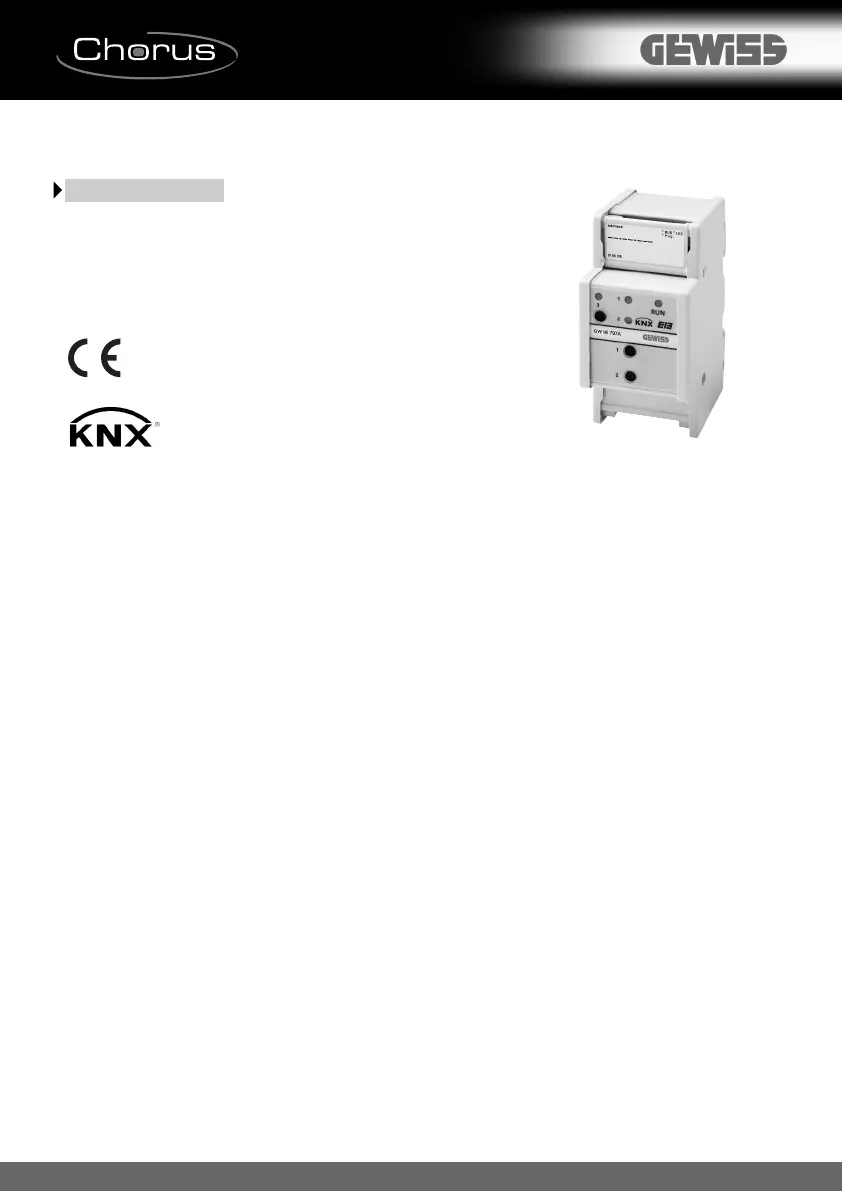
GW 90 797A
Modulo logico KNX
KNX logic module
Module logique KNX
Módulo lógico KNX
KNX-Logikmodul
Attenzione ! La sicurezza dell'apparecchio è garantita solo attenendosi alle istruzioni
qui riportate. Pertanto è necessario leggerle e conservarle.
I prodotti della gamma Chorus devono essere installati conformemente a quanto
previsto dalla norma CEI 64-8 per gli apparecchi per uso domestico e similare, in
ambienti non polverosi ed ove non sia necessaria una protezione speciale contro la
penetrazione di acqua.
L'organizzazione di vendita GEWISS é a disposizione per chiarimenti e informazioni
tecniche.
Warning !The safety of this appliance is only guaranteed if all the instructions given
here are followed scrupulously.
These should be read thoroughly and kept in a safe place.
Chorus product series can be installed in compliance with the requirements of HD 384 /
IEC364 standards covering equipment for domestic and similar uses in a dust-free
environment and where no special protection against the penetration of water is
required.
The GEWISS sales organization is ready to provide full explanations and technical
data on request.
Attention !La sécurité de l’appareil n’est garantie que si l’on respecte les
instructions mentionnées ci-joint.
Il est donc nécessaire de les lire avec attention et de bien les conserver.
Les produits de la gamme Chorus doivent être installés en conformité avec les
normes HD 384 / IEC364 sur les appareils à usage domestique et similaire, dans des
milieux non poussiéreux et où il n'est pas nécessaire d' avoir une protection spéciale
contre la pénétration d'eau. L'organisation de vente GEWISS est à votre disposition
pour toute élucidation ou information technique.
Atención !La seguridad del aparato está garantizada sólo si se respetan las
instrucciones aquí incluidas. Por lo tanto es necesario leerlas y conservalas.
Según lo dispuesto por las normas HD 384 / IEC364 referidas a los aparatos para
uso doméstico y similar, los productos de la gama Chorus se pueden instalar en
ambientes no polvorientos y en los lugares donde no se requiere una protección
especial contra la penetración del agua.
La organización de ventas GEWISS está a su disposición para aclaraciones e
informaciones técnicas.
Achtung !Die Sicherheit des Geräts ist nur durch Einhalten der hier aufgeführten
Anleitungen gewährleistet.
Diese müssen daher aufmerksam durchgelesen und sorgfältig aufbewahrt werden.
Die Produkte der Reihe Chorus sind für die Installation gemäß den Bestimmungen der
Normen HD 384 / IEC364 bezüglich Haushaltsgeräte u.ä. in staubfreien Räumen und
in Räumen, in denen keine spezielle Absicherung gegen das Eindringen von Wasser
erforderlich ist, bestimmt.
Die GEWISS-Verkaufsorganisation steht Ihnen für weitere technische Informationen
gerne zur Verfügung.
Product specificaties
| Merk: | Gewiss |
| Categorie: | Niet gecategoriseerd |
| Model: | GW90797A |
| Aantal kanalen: | - kanalen |
Heb je hulp nodig?
Als je hulp nodig hebt met Gewiss GW90797A stel dan hieronder een vraag en andere gebruikers zullen je antwoorden
Handleiding Niet gecategoriseerd Gewiss

1 Februari 2024
1 Februari 2024
1 Februari 2024
1 Februari 2024
1 Februari 2024
1 Februari 2024
1 Februari 2024
1 Februari 2024
1 Februari 2024
1 Februari 2024
Handleiding Niet gecategoriseerd
Nieuwste handleidingen voor Niet gecategoriseerd
8 Juni 2026
8 Juni 2026
8 Juni 2026
8 Juni 2026
8 Juni 2026
8 Juni 2026
8 Juni 2026
8 Juni 2026
8 Juni 2026
8 Juni 2026