Gewiss GW20483 Handleiding

Gewiss Rookmelder GW20483

Lees hieronder de 📖 handleiding in het Nederlandse voor Gewiss GW20483 (8 pagina's) in de categorie Rookmelder. Deze handleiding was nuttig voor 25 personen en werd door 2 gebruikers gemiddeld met 4.5 sterren beoordeeld

Pagina 1/8
Serie SYSTEM RF
PULSANTIERE RF
RF BUTTON PAD - TABLEAU DE COMMANDE RF - CAJA DE PULSADORES RF - DRUCKKNOPFTAFELN RF
PLACCHE TOP SYSTEM - TOP SYSTEM PLAQUES - PLAQUES TOP SYSTEM - PLACAS TOP SYSTEM - ABDECKRAHMEN TOP SYSTEM
Attenzione ! La sicurezza dell'apparecchio è garantita solo attenendosi
alle istruzioni qui riportate. Pertanto è necessario leggerle e
conservarle. I prodotti del programma System devono essere installati
conformemente a quanto previsto dalla norma CEI 64-8 per gli
apparecchi per uso domestico e similare, in ambienti non polverosi ed
ove non sia necessaria una protezione speciale contro la penetrazione di
acqua. L'organizzazione di vendita GEWISS é a disposizione per
chiarimenti e informazioni tecniche. I prodotti della serie System RF
sono conformi alla direttiva R&TTE 1999/5/CE marzo 1999. La tecnologia
radio utilizzata garantisce che più impianti System RF possano operare
senza interferenza nel medesimo edificio. La presenza di altri sistemi
radio, che trasmettono in modo permanente sulla stessa frequenza (868
MHz), può generare disturbi.
Warning ! The safety of this appliance is only guaranteed if all the
instructions given here are followed scrupulously. These should be read
thoroughly and kept in a safe place. Products of the System program can
be installed in compliance with the requirements of HD 384 / IEC364
standards covering equipment for domestic and similar uses in a dust-
free environment and where no special protection against the penetration of
water is required. The GEWISS sales organization is ready to provide full
explanations and technical data on request. The RF System series products
conform to Directive R&TTE 1999/5/EC March 1999. The radio technology
used guarantees that several RF System installations can operate in the
same building without interference. The presence of other radio systems
permanently transmitting on the same frequency (868 MHz) could cause
disturbances.
Attention ! La sécurité de l'appareil n'est garantie que si les instructions
suivantes sont respectées. Il est donc nécessaire de les lire avec attention
et de bien les conserver. Les produits de la série System doivent être
installés conformément à ce qui a été prévu par les normes CEI 64-8 pour
les appareils à usage domestique et similaires, dans des environnements
non poussiéreux et là où il n’est pas nécessaire de mettre en place une
protection spéciale contre la pénétration de l’eau. L’organisation de vente
Le placche in dotazione possono essere sostituite con una qualsiasi placca della serie TOP SYSTEM / VIRNA. - The plaques provided can be replaced by any plaque from the TOP SYSTEM / VIRNA series. -
Les plaques fournies peuvent être remplacées par n’importe quelle plaque de la série TOP SYSTEM / VIRNA. - Las placas que se suministran pueden sustituirse por una placa cualquiera de la serie
TOP SYSTEM / VIRNA. - Die zur Ausstattung gehörenden Abdeckrahmen können mit jedem Abdeckrahmen der Reihe TOP SYSTEM / VIRNA ersetzt werden.
de la Société GEWISS est à disposition pour tous éclaircissements et toutes
informations techniques. Les produits de la série System RF sont
conformes aux Normes R&TTE 1999/5/CE mars 1999. La technologie radio
utilisée garantit que plusieurs équipements System RF peuvent opérer en
même temps dans le même édifice sans aucune interférence. La présence
d’autres systèmes radio qui transmettent de façon permanente sur la même
fréquence (868 MHz) peut engendrer des perturbations.
¡ Atención ! La seguridad del aparato está garantizada sólo si se respetan
las instrucciones aquí indicadas. Por lo tanto es necesario leerlas y
conservalas. Los productos del programa System deben instalarse
conforme a lo previsto por la norma CEI 64-8 para los aparatos de uso
doméstico y similar, en ambientes sin polvo y donde no sea necesaria una
protección especial contra la penetración de agua. La organización de venta
GEWISS está a disposición para aclaraciones e informaciones técnicas. Los
productos de la serie System RF son conformes a la directiva R&TTE
1999/5/CE marzo 1999. La tecnología radio utilizada garantiza que más
instalaciones System RF pueden trabajar sin interferencia en el mismo
edificio. La presencia de otros sistemas radio, que transmiten
permanentemente en la misma frecuencia (868 MHz), puede generar
perturbaciones.
Achtung ! Die Sicherheit des Geräts ist nur durch Einhalten der hier
aufgeführten Anleitungen gewährleistet. Es ist daher notwendig, diese zu
lesen und aufzubewahren. Die Produkte des Programms System müssen
entsprechend der Vorgaben der Normen CEI 64-8 für Geräte mit Verwendung
in Wohngebäuden oder ähnlich eingebaut werden, in staubfreien Umgebungen
und an Orten wo kein besonderer Schutz gegen das Eindringen von Wasser
erforderlich ist. Die GEWISS Verkaufsorganisation steht für Aufklärungen
und technische Informationen zur Verfügung. Die Produkte der Reihe System
RF entsprechen den Richtlinien R&TTE 1999/5/CE - März 1999. Die
verwendete Funktechnologie garantiert dafür, dass mehrere System RF
Anlagen ohne Interferenzen im selben Gebäude arbeiten können. Die
Anwesenheit anderer Funksysteme, die permanent auf der selben Frequenz
(868 Mhz) senden, kann Störungen generieren.
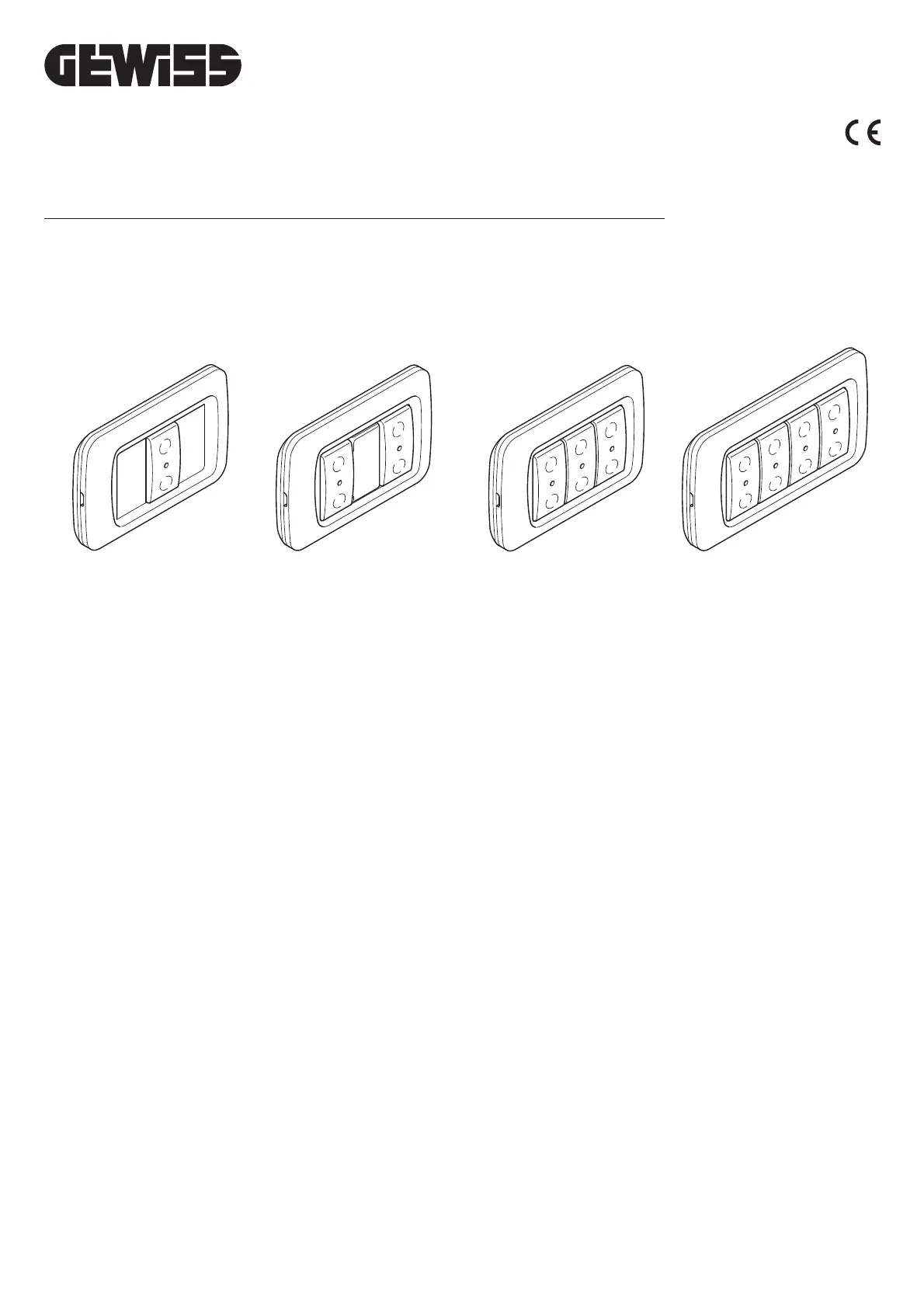
GW 20 991 - GW 21 991 GW 20 992 - GW 21 992 GW 20 993 - GW 21 993 GW 20 994 - GW 21 994
PLACCHE VIRNA - VIRNA PLAQUES - PLAQUES VIRNA - PLACAS VIRNA - ABDECKRAHMEN VIRNA
GW 20 891 - GW 21 891 GW 20 892 - GW 21 892 GW 20 893 - GW 21 893 GW 20 894 - GW 21 894
DESCRIZIONE
______________________________________________
Le pulsantiere RF permettono di comandare attuatori della serie SYSTEM RF quali:
•moduli di uscita 3A,
•moduli di uscita 16A,
•moduli per comando motore.
Le pulsantiere (1, 2, 3, 4 canali) sono dotate di un led verde (A) di segnalazione e di
un tasto (B) per ogni canale (C).
Ogni canale può essere associato ad un diverso attuatore.
Attraverso la pressione della parte superiore o inferiore del tasto è possibile
realizzare le funzioni di comando, come descritto in seguito.
CONFIGURAZIONE
________________________________________________
Per realizzare l’associazione con un modulo di uscita è sufficiente premere il tasto del
canale che di desidera abbinare, dopo aver posto il modulo di uscita in apprendimento
configurazione.
FUNZIONAMENTO
________________________________________________
Le funzioni di comando realizzabili dalle pulsantiere sono determinate dalla
selezione del modo di funzionamento operata sull’attuatore associato:
•in abbinamento con un modulo di uscita 3A o 16A, configurato in funzionamento
BISTABILE, ad esempio per il normale comando luci, si ottiene l’accensione della
luce (ON) premendo la parte superiore del tasto, lo spegnimento (OFF)
premendo la parte inferiore;
•in abbinamento con un modulo di uscita 3A o 16A, configurato in funzionamento
MONOSTABILE, ad esempio per il comando di un campanello, è possibile agire
indifferentemente sulla parte superiore o inferiore del tasto: premendo, si attiva il
carico, al rilascio il carico viene disattivato;
•in abbinamento con un modulo di uscita 3A o 16A, configurato in funzionamento
TEMPORIZZATO, ad esempio per la gestione luci scale, è possibile agire
indifferentemente sulla parte superiore o inferiore del tasto: premendo, le luci si
accendono (ON), al rilascio non si ottiene nessun effetto dato che lo
spegnimento delle luci (OFF) avviene automaticamente allo scadere della
temporizzazione impostata sull’attuatore;
•in abbinamento con un modulo di uscita per comando motore, ad esempio per
comando tapparelle, si ottiene la salita della tapparella agendo sulla parte
superiore del tasto, l’abbassamento agendo su quella inferiore. L’arresto si
ottiene agendo indifferentemente sulla parte superiore o inferiore del tasto
quando la tapparella è in movimento.
SEGNALAZIONI
____________________________________________________
Trasmissione di un comando
Alla pressione di un tasto qualsiasi, un lampeggio del led verde corrispondente indica
l’avvenuta trasmissione del comando.
Batterie in esaurimento
Alla pressione di un tasto qualsiasi, cinque lampeggi del led verde corrispondente
indicano che le batterie sono in fase di esaurimento. La trasmissione del comando è
comunque garantita. In tal caso è necessario procedere quanto prima alla
sostituzione delle batterie.
Se in seguito alla pressione di un tasto non si hanno indicazioni luminose,
verificare la presenza ed il corretto inserimento delle batterie ed,
eventualmente, sostituirle.
INSTALLAZIONE
____________________________________________
ATTENZIONE
•Prima dell’installazione assicurarsi che i moduli di uscita associati, ricevano
correttamente i comandi.
•
Nella fase di installazione rispettare il verso di montaggio indicato sul prodotto ( ).
Montaggio con tasselli
Montaggio con biadesivo
Montaggio su scatola 3 posti
Montaggio placche Top System / Virna
2
ITALIANO
Led verde di segnalazione
Tasto bilanciato
Canale
C
A
B
UP
2
1
3
2
1
2
1
2
1
Applicare la striscia isolante adesiva, in dotazione.
(Solo per placche colore cromo e oro.)
DESCRIPTION
______________________________________________
The RF button pads are used to control actuators of the RF SYSTEM series such as:
•3A output modules,
•16A output modules,
•motor control modules.
The button pads (1, 2, 3, 4 channels) are provided with a green signal LED (A) and
a key (B) for each channel (C).
Each channel can be associated to a different actuator.
The control functions, as described below, can be triggered by pressing the upper or
lower part of the key.
CONFIGURATION
________________________________________________
All that is required to make the association with an output module is to press the key
of the channel to be combined, after having set the output module in learn
configuration.
OPERATION
______________________________________________________
The control functions possible from the button pads are determined by the selection
of the operating mode made on the associated actuator:
•in combination with a 3A or 16A output module configured for BISTABLE
operation, for example for normal control of lights: the light is switched on (ON) by
pressing the upper part of the key and switched off (OFF) by pressing the lower
part;
•in combination with a 3A or 16A output module configured for MONOSTABLE
operation, for example for controlling a bell, it is possible to use either the upper
or the lower part of the key: the charge is activated when it is pressed and
disactivated when it is released;
•in combination with a 3A or 16A output module configured for TIMED operation,
for example for managing staircase lights. It is possible to use either the upper or
lower part of the key: the lights are switched on (ON) when it is pressed; there is
no effect when it is released since the lights are switched off (OFF) automatically
when the time set on the actuator has elapsed;
•in combination with an output module for motor control, for example for
controlling roller blinds: the blind is raised by using the upper part of the key and
lowered by using the lower. The blind is stopped by using either the upper or
lower part of the key when it is in motion.
SIGNALS
____________________________________________________________
Transmission of a command
When any key is pressed, a blink of the corresponding green LED shows that a
command has been transmitted.
Batteries discharged
When any key is pressed, five blinks of the corresponding green LED show that the
batteries are becoming discharged. Transmission of the command is guaranteed in
any case. In this case, the batteries must be replaced as soon as possible.
If there are no light signals when a button is pressed, check that the batteries
are present and fitted correctly, and replace them if necessary.
INSTALLATION
____________________________________________________
WARNING
•Before installation ensure that the associated output modules receive the
commands correctly.
•During the installation stage respect the assembly sequence shown on the
product ( ).
Assembly with wall-plugs
Assembly with two-face adhesive tape
SOSTITUZIONE BATTERIE
__________________________________
Non disperdere le batterie scariche nell’ambiente
DATI TECNICI
________________________________________________
- Temperatura operativa -5° +40°C
- Frequenza radio 868 MHz
- Portata radio 100 m in campo libero
- Alimentazione a batteria, 2x1,5V alcaline tipo AAA
- Dimensioni max.(B x L x H) 116x80x22 mm
3
ENGLISH
Green signal LED
Balanced key
Channel
C
A
B
2
1
3
2
1
1
23
4
n.2 batterie alcaline 1,5V, tipo AAA
UP


Product specificaties

Merk: Gewiss
Categorie: Rookmelder
Model: GW20483
Kleur van het product: Wit
Breedte: 176 mm
Diepte: 75 mm
Hoogte: 125 mm
Stroombron: Batterij/Accu
Detector type: Optische detector
Licht alarm: Ja

Heb je hulp nodig?

Als je hulp nodig hebt met Gewiss GW20483 stel dan hieronder een vraag en andere gebruikers zullen je antwoorden


Handleiding Rookmelder Gewiss

Gewiss

Gewiss GW20483 Handleiding

1 Februari 2024

Handleiding Rookmelder

Nieuwste handleidingen voor Rookmelder