Garmin LIDAR-Lite v4 LED Handleiding
Garmin Niet gecategoriseerd LIDAR-Lite v4 LED
Bekijk gratis de handleiding van Garmin LIDAR-Lite v4 LED (10 pagina’s), behorend tot de categorie Niet gecategoriseerd. Deze gids werd als nuttig beoordeeld door 36 mensen en kreeg gemiddeld 4.0 sterren uit 6 reviews. Heb je een vraag over Garmin LIDAR-Lite v4 LED of wil je andere gebruikers van dit product iets vragen? Stel een vraag
Pagina 1/10
LIDAR-LITE V4 LED
OPERATION MANUAL AND
TECHNICAL SPECIFICATIONS
Specifications
Specification Measurement
Unit dimensions (L × W × H)
NOTE: Measurements do not
include an attached connector.
52.2 x 24 x 21.2 mm (2.1 x 0.9 x
0.8 in.)
Weight14.6 g (0.5 oz.)
Operating temperature-20 to 60°C (-4 to 140°F)
Storage temperature-40 to 85°C (-40 to 185°F)
Power (operating voltage)4.75 to 5.25 Vdc
Current consumption2 mA idle
85 mA during an acquisition
Input voltage (VIN)3.3 V Max
Range5 cm (1.97 in.) to 10 m (32.8 ft.)
Resolution1 cm (0.4 in.)
Beam divergence4.77 degrees
LED wavelength940 nm
Optical aperture14.9 mm
Update rateI2C: Greater than 200 Hz typical
ANT: Up to 200 Hz to a 90%
reflective target indoors at 2 m in
normal operating mode
InterfaceI2C or ANT®
Configurable for SPI with user
applications
Measurement repeatability
NOTE: As measured indoors to a
90% reflective target; 1 cm is
equivalent to 1 standard deviation.
Measurements were obtained
using high accuracy mode.
± 1 cm to 2 m
± 2 cm to 4 m
± 5 cm to 10 m
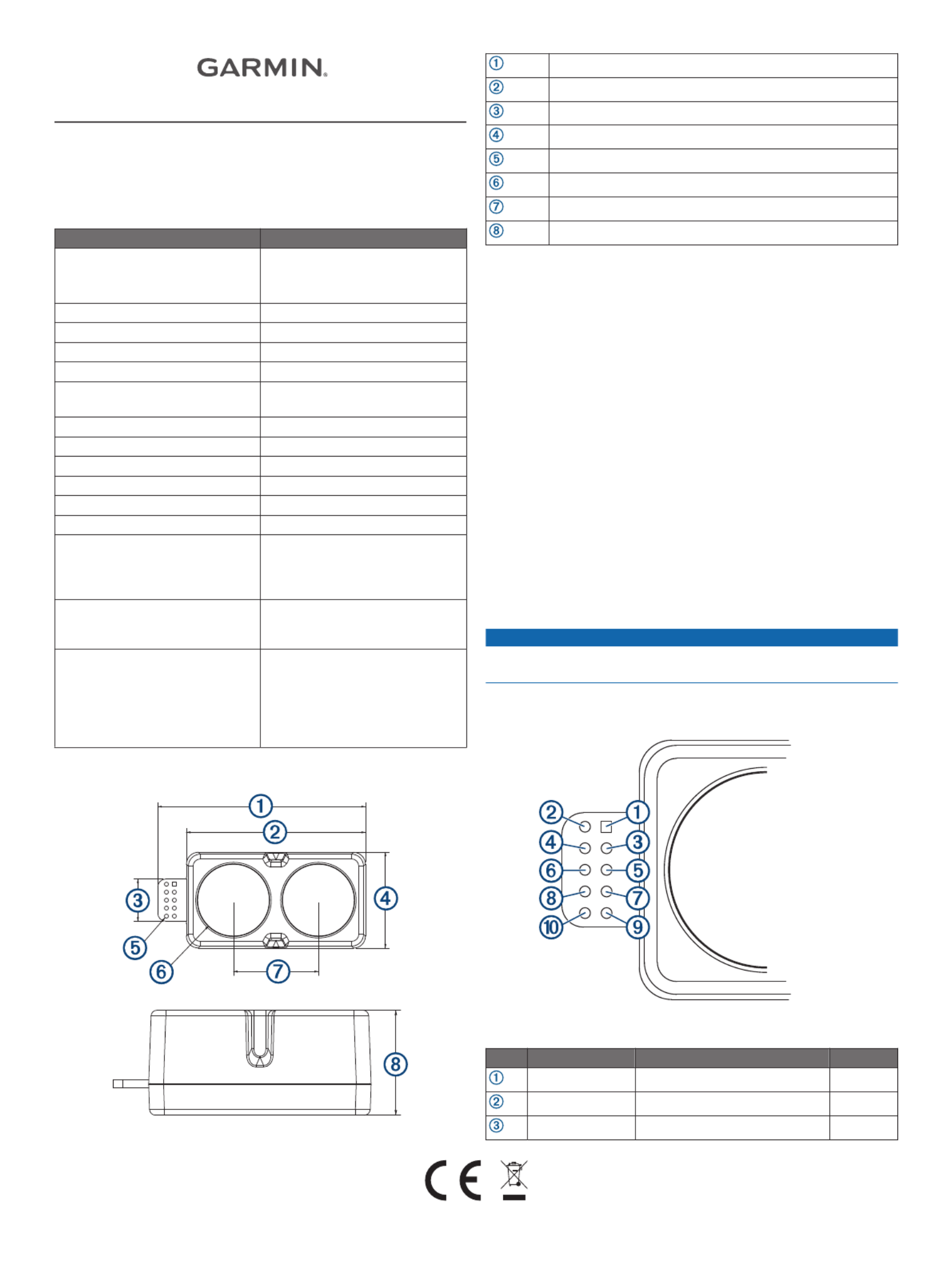
Device Dimensions
52.17 mm (2.05 in.)
44.98 mm (1.77 in.)
10.6 mm (0.42 in.)
24.03 mm (0.95 in.)
1 mm (0.04 in.)
18 mm (0.71 in.)
21.35 mm (0.84 in.)
21.2 mm (0.83 in.)
Mounting Options
Cable tie: You can secure the device to your application using a
3.6 mm (0.14 in.) wide cable tie. You should route the cable
tie through the channel in the center of the device.
Double-sided tape: You can secure the bottom of the device to
your application using double-sided tape. For best results,
you should select a tape that has a high-strength bond.
Labeling Requirements
The LIDAR-Lite v4 LED device is an FCC-certified transmitter. If
you are integrating the device with another product, you must
ensure the FCC ID is visible from the outside of your product.
You are responsible for meeting any other labeling requirements
imposed by the FCC rules and any rules related to the
compliance of your end product.
Connections
LIDAR-Lite v4 LED Connection Diagram
The through-holes on the LIDAR-Lite v4 LED device are
arranged in 2 rows of 5 holes each, with a 2 mm pitch between
each connection.
NOTICE
The LIDAR-Lite v4 LED maximum signal level is 3.3 V. A signal
greater than 3.3 V will damage the device.
PinPin NameFunctionV Max
VIN5 V Power5 V
GND Ground--
I2C SDAI2C Data3.3 V
GUID-48127269-EFD8-41FF-93EC-D21B0A1EFE74 v2September 2020
Product specificaties
| Merk: | Garmin |
| Categorie: | Niet gecategoriseerd |
| Model: | LIDAR-Lite v4 LED |
Heb je hulp nodig?
Als je hulp nodig hebt met Garmin LIDAR-Lite v4 LED stel dan hieronder een vraag en andere gebruikers zullen je antwoorden
Handleiding Niet gecategoriseerd Garmin

12 Februari 2026
12 Februari 2026
11 Februari 2026
31 December 2026
30 December 2026
8 November 2025
11 Augustus 2025
7 Mei 2025
25 Februari 2025
9 Januari 2025
Handleiding Niet gecategoriseerd
Nieuwste handleidingen voor Niet gecategoriseerd
7 Juni 2026
7 Juni 2026
7 Juni 2026
7 Juni 2026
6 Juni 2026
6 Juni 2026
6 Juni 2026
6 Juni 2026
6 Juni 2026
6 Juni 2026