Frigidaire PLMV169DC Handleiding
Frigidaire
Magnetron
PLMV169DC
Bekijk gratis de handleiding van Frigidaire PLMV169DC (8 pagina’s), behorend tot de categorie Magnetron. Deze gids werd als nuttig beoordeeld door 33 mensen en kreeg gemiddeld 4.6 sterren uit 17 reviews. Heb je een vraag over Frigidaire PLMV169DC of wil je andere gebruikers van dit product iets vragen? Stel een vraag
Pagina 1/8

1
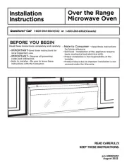
1 MOUNTING SPACE
This Microwave Oven/Hood requires a mounting space on a
wall as shown in Figure 1. It is designed to be used with stan-
dard 12-inch wall cabinets.
p/n 2 316137 34
TINSEB385MRR0
2 WALL CONSTRUCTION
This Microwave Oven/Hood should be mounted against and
supported by a flat vertical wall. The wall must be flat for prop-
er installation. If the wall is not flat, use spacers to fill in the
gaps. Wall construction should be a minimum of 2” x 4” wood
studding and 3/8” or more thick dry wall or plaster/lath. The
mounting surfaces must be capable of supporting weight of 110
pounds—the oven and contents—AND the weight of all items
which would normally be stored in the top cabinet above the
unit.
The unit should be attached to a minimum of one 2” x 4”
wall stud or two 2" x 3" wall studs.
To find the location of the studs, one of the following methods
may be used:
A. Use a stud finder, a magnetic device which locates the nails
in the stud.
B. Use a hammer to tap lightly across the mounting surface to
find a solid sound. This will indicate stud location.
The center of the stud can be located by probing the wall with a
small nail to find the edges of the stud and then placing a mark
halfway between the edges. The center of any adjacent studs
will normally be 16” or 24” to either side of this mark.
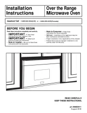
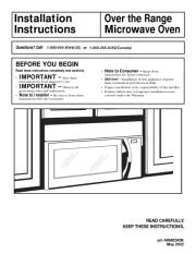
Installation
Instructions
Over the Range
Microwave Oven
BEFORE YOU BEGIN
•IMPORTANT – Save these instructions for local
inspector's use.
•IMPORTANT – Observe all governing codes
and coordinates.
•Note to Installer – Be sure to leave these
instructions with the Consumer.
•Note to Consumer – Keep these instruc-
tions for future reference.
•Skill Level – Installation of this appliance
requires basic mechanical and electrical skills.
• Proper installation is the responsibility of the installer.
• Product failure due to improper installation is not cov-
ered under the Warranty.
• Please read all instructions thoroughly before installing
the Over the Range Microwave Oven. Two people are
recommended to install this product.
• If a new electrical outlet is required, its installation
should be completed by a qualified electrician before the
Microwave Oven is installed. See 3 ELECTRICAL
GROUNDING INSTRUCTIONS on page 2.
Read
these instructions completely and carefully.
NEED HELP?
For customers in the United States, call: 1-800-944-9044
For customers in Canada, call: 1-800-213-9397 (English)
1-800-668-4606 ext.8199 (French)
READ CAREFULLY. KEEP THESE INSTRUCTIONS.
Figure 1
66" or more
from floor
Backsplash At least 2"
15.5"
30"
12"
30" or more from
cooking surface

2
3 ELECTRICAL GROUNDING
INSTRUCTIONS
This appliance must be grounded. This oven is equipped with a
cord having a grounding wire with a grounding plug. It must be
plugged into a wall receptacle that is properly installed and
grounded in accordance with the National Electrical Code and
local codes and ordinances. In the event of an electrical short
circuit, grounding reduces risk of electric shock by providing an
escape wire for the electric current.
WARNING - Improper use of the grounding plug can result in a
risk of electric shock.
ELECTRICAL REQUIREMENTS
The oven is equipped with a 3-prong grounding plug. DO NOT
UNDER ANY CIRCUMSTANCES CUT OR REMOVE THE
GROUNDING PIN FROM THE PLUG.
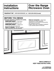
The Power Supply Cord and plug must be connected to a sep-
arate 120 Volt AC, 60 Hz, 15 Amp, or more branch circuit, sin-
gle grounded receptacle. The receptacle should be located
inside the cabinet directly above the Microwave Oven mounting
location as shown in Figure 2.
NOTE:
1. If you have any questions about the grounding or electrical
instructions, consult a qualified electrician or serviceperson.
2. Neither Electrolux nor the dealer can accept any liability for
damage to the oven or personal injury resulting from failure
to observe the correct electrical connection procedures.
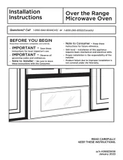
4 HOOD EXHAUST DUCT
When the hood is vented to the outside, a hood exhaust duct is
required. All ductwork must be metal; absolutely do not use
plastic duct. Check that all connections are made securely.
Please read the following carefully:
Exhaust connection: The hood exhaust has been designed to
connect to a standard 3-1/4” X 10” rectangular duct. If round
duct is required, a rectangular-to-round adapter must be used.
Rear exhaust: If a rear or horizontal exhaust is to be used, care
should be taken to align the exhaust with the space between the
studs, or wall should be prepared at the time it is constructed by
leaving enough space between wall studs to accommodate
exhaust.
Maximum duct length: For satisfactory air movement, the total
duct length of 3-1/4” X 10” rectangular or 6” diameter round duct
should not exceed 140 feet.
Elbows, adapters, wall caps, roof caps, etc. present additional
resistance to air flow and are equivalent to a section of straight
duct which is longer than their actual physical size. When calcu-
lating the total length, add the equivalent lengths of all transi-
tions and adapters plus the length of all straight duct sections.
Figure 3 shows the approximate feet of equivalent length of
some typical ductwork parts. Use the values in parentheses for
calculating air flow resistance equivalent, which should total
less than 140 feet.
Installation Instructions
Figure 2
Ground
Receptacle
Opening for
Power Cord
Figure 3

3
5 TOOLS RECOMMENDED FOR
INSTALLATION
• Phillips Screwdriver
• Electric Drill
• 1/2”, 5/8” and 3/32” Drill Bits
• 1-1/2” Wood Bit or Metal Hole Cutter
(if metal cabinet is used)
• Saw to cut exhaust opening (if needed)
• Protective Drop Cloth for product and range -
you may also use carton for protection
• Scissors
• Pencil
• Measure
• Tape
6 INSTALLATION HARDWARE
The INSTALLATION HARDWARE (items 1 - 8) packed with
the oven should contain the following:
Item Name Quantity
1Wood Screw 5 X 30 mm 6
2Toggle Bolt 3/16 inch 4
3Top Cabinet Screw 5 X 60 mm 2
4Flat Washer 30 mm diameter 2
5Power Cord Hanger 1
6Grommet 1
7Tapping Screw 4 x 12 mm 4
8Exhaust Damper Assembly 1
9Charcoal Filter 1
Installation Instructions
Figure 4
Parts shown not to common scale.
7 PREPARATION OF THE OVEN
1. Open the bottom of the carton, bend the carton flaps back
and tilt the oven over to rest on plastic foam pad. Lift carton
off oven and remove all packing materials, Installation
Instructions, Wall Template, Top Template, Charcoal Filter,
Turntable and Turntable Support; however, DO NOT
REMOVE THE WAVEGUIDE COVER, which is located on
the ceiling in the oven cavity. SAVE THE CARTON AS IT
MAY MAKE INSTALLATION EASIER.
2. CHECK THE OVEN.
Check the oven for any damage, such as misaligned or bent
door, damaged door seals and sealing surfaces, broken or
loose door hinges and latches and dents inside the cavity or
on the door. If there is any damage, do not operate the oven
and contact your dealer or ELECTROLUX AUTHORIZED
SERVICER.
3. Remove and save Screws (A) as shown in Figure 5.
4. Pull the louver away from the unit and set aside.
5. Loosen the two Mounting Screws (D) which secure the
Mounting Plate to the rear side of the oven. Remove the
Mounting Plate. See Figure 6.
Figure 5
Control
Panel
Side
(D)
Mounting
Plate
(D)
Mounting Plate
(A)
Figure 6
(A)
(A)
(A)
Product specificaties
| Merk: | Frigidaire |
| Categorie: | Magnetron |
| Model: | PLMV169DC |
Heb je hulp nodig?
Als je hulp nodig hebt met Frigidaire PLMV169DC stel dan hieronder een vraag en andere gebruikers zullen je antwoorden
Handleiding Magnetron Frigidaire
13 Mei 2025
13 Mei 2025

13 Mei 2025
13 Mei 2025
13 Mei 2025

13 Mei 2025
13 Mei 2025
13 Mei 2025
13 Mei 2025

13 Mei 2025
Handleiding Magnetron
- Haden
- Saro
- Merrychef
- Respekta
- SEB
- Brother
- DCS
- Bosch
- Café
- Bauknecht
- Technika
- Delonghi
- Xiaomi
- Pitsos
- Summit
Nieuwste handleidingen voor Magnetron
30 Juli 2025
29 Juli 2025

29 Juli 2025

28 Juli 2025
28 Juli 2025
28 Juli 2025
28 Juli 2025
28 Juli 2025

28 Juli 2025
28 Juli 2025