Frigidaire F36WC19EB Handleiding
Frigidaire
Ventilator
F36WC19EB
Bekijk gratis de handleiding van Frigidaire F36WC19EB (8 pagina’s), behorend tot de categorie Ventilator. Deze gids werd als nuttig beoordeeld door 52 mensen en kreeg gemiddeld 4.8 sterren uit 26.5 reviews. Heb je een vraag over Frigidaire F36WC19EB of wil je andere gebruikers van dit product iets vragen? Stel een vraag
Pagina 1/8

1
WARNING
TO REDUCE THE RISK OF FIRE, ELECTRIC SHOCK, OR IN-
JURY TO PERSONS, OBSERVE THE FOLLOWING:
1. Use this unit only in the manner intended by the manufac-
turer. If you have questions, contact the manufacturer at
the address or telephone number listed in the warranty.
2. Before servicing or cleaning unit, switch power off at ser-
vice panel and lock the service disconnecting means to
prevent power from being switched on accidentally. When
the service disconnecting means cannot be locked, securely
fasten a prominent warning device, such as a tag, to the
service panel.
3. Installation work and electrical wiring must be done by a
qualified person(s) in accordance with all applicable codes
and standards, including fire-rated construction codes and
standards.
4. Sufficient air is needed for proper combustion and exhaust-
ing of gases through the flue (chimney) of fuel burning equip-
ment to prevent backdrafting. Follow the heating equipment
manufacturer’s guideline and safety standards such as those
published by the National Fire Protection Association (NFPA),
and the American Society for Heating, Refrigeration and Air
Conditioning Engineers (ASHRAE), and the local code au-
thorities.
5. When cutting or drilling into wall or ceiling, do not damage
electrical wiring and other hidden utilities.
6. Ducted fans must always be vented to the outdoors.
7. Do not use this unit with any solid-state speed control de-
vice.
8. To reduce the risk of fire, use only metal ductwork.
9. Use with approved cord-connection kit only.
10. This unit must be grounded.
TO REDUCE THE RISK OF A RANGE TOP GREASE FIRE:
1. Never leave surface units unattended at high settings.
Boilovers cause smoking and greasy spillovers that may
ignite. Heat oils slowly on low or medium settings.
2. Always turn hood ON when cooking at high heat or when
cooking flaming foods.
3. Clean ventilation fans frequently. Grease should not be al-
lowed to accumulate on fan or filter.
4. Use proper pan size. Always use cookware appropriate for
the size of the surface element.
IMPORTANT
For Non-ducted (Ductfree) Installation:
a) Purchase non-ducted filter separately.
b) Remove and discard damper/duct connector and louver cover
(See Step 4) in “Prepare the Hood,” Page 2.
c) Follow all steps except steps inside dotted lines.
For Ducted Installation:
Follow all steps, including steps inside dotted lines.
F30WC, F36WC, & F42WC SERIES
4-WAY CONVERTIBLE RANGE HOOD
READ AND SAVE THESE INSTRUCTIONS
!
INTENDED FOR DOMESTIC COOKING ONLY
!
TO REDUCE THE RISK OF INJURY TO PERSONS IN THE
EVENT OF A RANGE TOP GREASE FIRE, OBSERVE THE
FOLLOWING:*
1. SMOTHER FLAMES with a close-fitting lid, cookie sheet, or
metal tray, then turn off the burner. BE CAREFUL TO PRE-
VENT BURNS. If the flames do not go out immediately, EVACU-
ATE AND CALL THE FIRE DEPARTMENT.
2. NEVER PICK UP A FLAMING PAN - You may be burned.
3. DO NOT USE WATER, including wet dishcloths or towels -
a violent steam explosion will result.
4. Use an extinguisher ONLY if:
A. You know you have a Class ABC extinguisher and you
already know how to operate it.
B. The fire is small and contained in the area where it started.
C. The fire department is being called.
D. You can fight the fire with your back to an exit.
* Based on “Kitchen Fire Safety Tips” published by NFPA.
CAUTION
!
1. For general ventilating use only. Do not use to exhaust
hazardous or explosive materials and vapors.
2. To avoid motor bearing damage and noisy and/
or unbalanced impellers, keep drywall spray,
construction dust, etc. off power unit.
3. Your hood motor has a thermal overload which will automatically
shut off the motor if it becomes overheated. The motor will
restart when it cools down. If the motor continues to shut off
and restart, have the hood serviced.
4. For best capture of cooking impurities, your range hood should
be mounted 18-24" above the cooking surface.
5. Please read specification label on product for further information
and requirements.
WARNING
INSTALLER: Leave This Manual With
the Homeowner.
HOMEOWNER: Use and Care
Information on Page 5.

2
FIG. 1B
FIG. 1C
FIG. 1D
FIG. 1E
6" ROUND DUCT 3-1/4" x 10"
TO 6"
ROUND
DUCT
TRANSITION
WALL CAP
WALL CAP
3-1/4" x 10" DUCT
ROOF CAP
3-1/4" x 10" DUCT
ADJUSTABLE ELBOW
WALL CAP
3-1/4" x 10" TO
6" ROUND
DUCT
TRANSITION
ROOF CAP
6" ROUND
DUCT
TOOLS AND
MATERIALS REQUIRED
TOOLS
❏Drill, electric or ratchet drive
❏1-1/4" Spade bit
❏Common head and phillips head screwdriver
❏Pliers
❏Tape measure or ruler and pencil
For Ducted Installations ONLY:
❏ Saber saw or drywall saw
❏ Metal snips
MATERIALS
❏Electrical wiring and supplies of type to comply with local
codesFor Ducted Installations Only:
❏ Roof or wall cap
❏ Roof cement or caulk
❏ Duct and duct tape
For Installation on Kitchen Cabinets with Recessed Bottoms
Only:
❏Two 1" x 2" x 12" (approximate length) wood strips (pur-
chase locally)
❏Four 1-1/4" long flat head wood screws (purchase locally)
to fasten strips to cabinet bottom
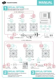
PLANNING DUCTWORK
INSTALLATION
Begin planning ductwork by deciding where the duct will run
between the range hood and the outside. For best performance,
use the shortest possible duct run and a minimum number of
elbows. There are several choices shown - FIGS. 1A - 1E.
In more complex ducting situations, a 3-1/4" rectangular ducting
range hood can be converted to a round duct by means of a
transition.
FIG. 1A. Ducting directly through the wall (for range hoods
mounted on an exterior wall). Shown are two ways to duct through
an outside wall. If a wall cap is used directly off the back of the
hood, special care must be taken to make sure that the damper
in the damper/duct connector on the hood and damper in the
wall cap do not interfere with each other when the hood is oper-
ating. This could result in either inadequate air delivery or back
drafts. If this condition does exist, remove the hood damper flap.
Sometimes when using a wall cap it is easier to duct vertically
and then use an elbow as shown in FIG. 1B.
FIG. 1C. Ducting straight up through the roof using
3-1/4" x 10" rectangular duct. (For single story installations.)
FIG. 1D. Ducting between the ceiling joists (for multi-story instal-
lations) or through the soffit space above the cabinets (where
the soffit connects to an outside wall).
FIG. 1E. Straight up through the roof using 3-1/4” x 10” to 6”
round duct transition and 6" round duct (for single-story installa-
tions).
FIG. 1F. Straight up through the roof using 7" round duct (for
single-story installations). Requires optional damper Model Damp
Kit available from your local dealer.
FIG. 1A
7" ROUND DUCT
DAMPER
MODEL
“DAMPKIT”
ROOF CAP
FIG. 1F

3
FIG. 2
FIG. 5
FIG. 6
FIG. 7
CUT STRIPS TO FIT
CENTER
LINE
WIDTH OF
RANGE
HOOD
ELECTRICAL
WIRING OPENING
FIG. 3
DUCT
OPENINGS
PREPARING THE RANGE HOOD
1. Unpack hood and check contents. You should receive:
1 - Aluminum Filter
1 - 3-1/4" x 10" Damper/Duct Connector (mounted inside of
hood for shipping only) (Save screws for mounting.)
1 - 7” Round Duct Plate (mounted on top of hood) (not shown)
(Save screws for mounting.)
2. Remove 7” round duct plate from top of hood. Set duct plate
aside - with mounting screws.
3. Remove wiring box cover. Under cover find:
PREPARING THE
INSTALLATION LOCATION
FIG. 4
WIRING BOX
COVER
DAMPER/DUCT CONNECTOR
ALUMINUM
FILTER
For Ductfree Installations Only:
4. For ductfree installation, remove louver cover from front (or
inside) of hood. (FIG. 3)
NOTE
Louvers on front of hood must be open and visible
for hood to function in ductfree mode.
5. Remove either top or rear electrical knockout depending upon
whether wiring will enter hood from wall or cabinet. (FIG. 4)
DUCTED INSTALLATION ONLY
NOTE
Louver cover must be installed as shown in Figure 3 to
function in ducted mode.
6. Remove appropriate duct knockout on hood by inserting
screwdriver into edge of knockout and breaking tabs holding
knockout to hood. You may have to tap screwdriver with ham-
mer to break tabs. Peel knockout back with pliers. (FIG. 5)
7. Fit damper/duct connector over opening and secure in place with
black sheet metal screws. (FIG. 6)
Hinge pins and damper/duct connector should be toward top
of hood for ducting through wall or toward back of hood for
ducting through cabinet above hood. Seal joint between
damper/duct connector and hood with duct tape.
8. 7” round ducted discharge only: Re-install 7” round duct
plate removed in Step #2 under “PREPARING THE RANGE
HOOD” section. For best performance, line up the 7” round
duct plate with the 7” round opening on hood. Mount duct
plate to hood with 2 screws from duct plate and 2 screws
from 3¼” x 10” damper. Install a 7” round damper (purchase
separately). Damper flap must open freely in direction of air
flow (away from range hood).
KEYHOLE SLOTS
NOTE
MOUNT HOOD SO THAT BOTTOM OF HOOD IS 18"-24" ABOVE
COOKING SURFACE. TOP FRONT EDGE OF HOOD SHOULD
BE FLUSH WITH FRONT OF CABINET FRAME.
IF DISTANCE BETWEEN WALL AND FRONT OF CABINET
FRAME IS MORE THAN 12" THERE WILL BE A SPACE BE-
TWEEN BACK OF HOOD AND WALL. THIS IS NORMAL.
OMIT STEP 9 if range hood will be installed under cabinets
with flush bottom.
9. (For installation on recessed bottom cabinets only) Attach a
wood filler strip at each side of recessed area under cabi-
net. (Use two 1" x 2" strips cut to length.) If recess is more
than 1" use thicker strips. Attach strips with 1-1/4" screws
about 3" from each end. See FIG. 7.
10.Measure and mark the following (FIGS. 7 & 8):
a) Electrical line opening
b) Duct opening
11.Drill four pilot holes in corners of marked duct opening as
shown and cut opening with saber saw or keyhole saw.
12.Use 1-1/4" drill bit to drill opening for electrical connection
in wall or cabinet.
13.Hold hood up against cabinet bottom and trace keyhole slots
onto cabinet bottom of filler strips.
14.Screw the four supplied 7/8" wood screws for mounting the
hood into the exact center of the narrow end of the keyhole
slots marked underneath the cabinet. Allow 3/8" of the
screws to project, so the hood can be fitted into place.
Product specificaties
| Merk: | Frigidaire |
| Categorie: | Ventilator |
| Model: | F36WC19EB |
Heb je hulp nodig?
Als je hulp nodig hebt met Frigidaire F36WC19EB stel dan hieronder een vraag en andere gebruikers zullen je antwoorden
Handleiding Ventilator Frigidaire

26 December 2023

26 December 2023

4 Juni 2023

18 Mei 2023

14 Mei 2023

2 Mei 2023

29 April 2023

25 April 2023

24 April 2023

16 April 2023
Handleiding Ventilator
- Powerplus
- Carrier
- Proficare
- Melissa
- EXCELLENT Electrics
- Phaesun
- Esperanza
- Vitammy
- Beurer
- Hornbach
- Crane
- H.Koenig
- Klarbach
- Falmec
- OK
Nieuwste handleidingen voor Ventilator
30 Juli 2025

29 Juli 2025
29 Juli 2025
29 Juli 2025

28 Juli 2025

23 Juli 2025

23 Juli 2025

22 Juli 2025

22 Juli 2025

22 Juli 2025