Festo VOVK-BT6-M32C-MN-5H5ZP-FB Handleiding
Festo Niet gecategoriseerd VOVK-BT6-M32C-MN-5H5ZP-FB
Bekijk gratis de handleiding van Festo VOVK-BT6-M32C-MN-5H5ZP-FB (3 pagina’s), behorend tot de categorie Niet gecategoriseerd. Deze gids werd als nuttig beoordeeld door 49 mensen en kreeg gemiddeld 4.3 sterren uit 7 reviews. Heb je een vraag over Festo VOVK-BT6-M32C-MN-5H5ZP-FB of wil je andere gebruikers van dit product iets vragen? Stel een vraag
Pagina 1/3
VOVK miniature solenoid valve
†‡
Festo SE & Co. KG
Ruiter Straße 82
73734 Esslingen
Germany
+49 711 347
-0
www.festo.com
AssemblyInstruction s
8149389
2020
- 11a
[8149390]
Miniature switching valve VOVKsolenoid ......................................... English
1Other applicable documents
All documents for the product are available at
www.festo.com/sp
2 Safety
2.1S afety instructions
- Switch off the power supply before carrying out any assembly work.
-Switch off the media supply before carrying out any assembly work.
- Only mount product on components that are in a safe condition.
-Only use the product in its original condition without unauthorized
modifications.
-The product must not be used if the product is dirty or damaged as a
result of damaged packaging.
-Assembly and installation by qualified personnel only.
2.2Intended Use
The valves are solenoid switching valves for air and are intended to release,
block or change the flow of air.
2.3Foreseeable Misuse
-The product may not be used outside the limits of the product defined
by the technical data.
- The product must not be used in a potentially explosive atmosphere.
- The product cannot be used for oxygen or aggressive gases
- The product cannot be used for liquids
3Scope of Delivery
Each VOVK valve comes with a set of mounting plates and screws:
- 2 mounting plates for ends
- 2 screws
The VOVK-…-FB type ( flange mount)comes with one additionalplate:
- 1 mounting plate for intermediate position
For the VOVK valves with cable/connector also the 30cm cable is always
included with the valve.
4 Assembly
Assembly and installation by qualified personnel only.
- Switch off the power supply before carrying out any assembly work.
-Switch off the media supply before carrying out any assembly work.
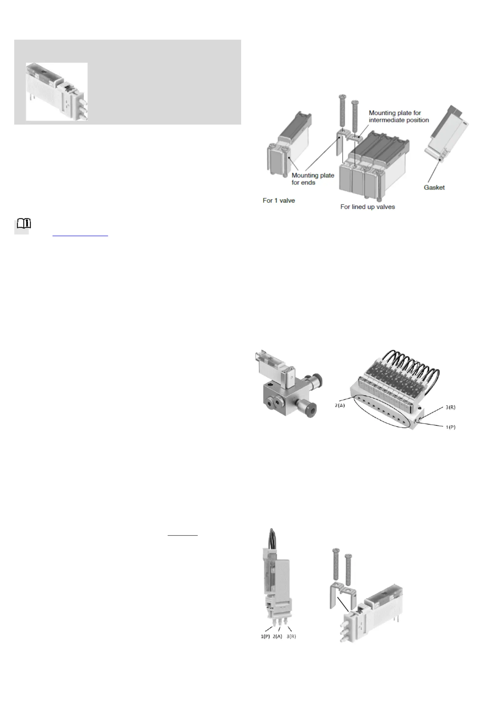
4.1VOVK-…-FB type (flange mount)
This type of VOVK valve has the flange connection at the bottom and fits to
the manifold for a single valve or for 10 valves.
D10--epending on the position of the valve on the valvemanifold you will
n eed the mounting plates for end and/or intermediate position.
For 1 valve
1. Put the valve on the base, attach mounting plates for ends.
2. Tighten the screws provided to a tightening torque of 17.6 Ncm
[1.558 in・lbf].
Note: Tighten the screws evenly so the valve does not tilt.
For multiple valves that are lined up
1. Line up the valves on the base, attach the mounting plates for
intermediate positions and for ends.
2. Tighten the screws provided to a tightening torque of 17.6 Ncm
[1.558 in・lbf].
Note: Use the valves in a line at a 6 mm [0.236 in] pitch.
The mounting plates provided (intermediate) are for a 6 mm [0.236 in] pitch.
4.2VOVK-…- B3F/B3.2F (single valves)
This type of VOVK valve has the direct barb connections.
You will need the two mounting plates for the ends and the screws to mount
them in a similar way as the VOVK-...-FB type above.
Product specificaties
| Merk: | Festo |
| Categorie: | Niet gecategoriseerd |
| Model: | VOVK-BT6-M32C-MN-5H5ZP-FB |
Heb je hulp nodig?
Als je hulp nodig hebt met Festo VOVK-BT6-M32C-MN-5H5ZP-FB stel dan hieronder een vraag en andere gebruikers zullen je antwoorden
Handleiding Niet gecategoriseerd Festo

3 Mei 2026
30 April 2026
29 April 2026
29 April 2026
29 April 2026
29 April 2026
28 April 2026
28 April 2026
28 April 2026
28 April 2026
Handleiding Niet gecategoriseerd
Nieuwste handleidingen voor Niet gecategoriseerd
23 Juli 2026
23 Juli 2026
23 Juli 2026
23 Juli 2026
23 Juli 2026
23 Juli 2026
22 Juli 2026
22 Juli 2026
22 Juli 2026
22 Juli 2026