Festo MS9-LFM Handleiding
Festo Niet gecategoriseerd MS9-LFM
Bekijk gratis de handleiding van Festo MS9-LFM (2 pagina’s), behorend tot de categorie Niet gecategoriseerd. Deze gids werd als nuttig beoordeeld door 8 mensen en kreeg gemiddeld 4.1 sterren uit 2 reviews. Heb je een vraag over Festo MS9-LFM of wil je andere gebruikers van dit product iets vragen? Stel een vraag
Pagina 1/2
Warnung,Warning
.....................................
deUnterDruckluftstehendeProduktekönnen
Personen-oderSachschädenverursachen.
•SchaltenSievorInstallations-und
WartungsarbeitendieDruckluftversorgungaus.
•VerwendenSiezurEntlüftungderAnlage
AbsperrventileinderDruckluftzuleitung.
enDevicesundercompressedairpressurecancause
injurytohumanbeingsanddamagetoproperty.
•Beforecarryingoutinstallationandmaintenance
workalwaysswitchoffthecompressedair
supply.
•Useshut-offvalvesinthecompressedairtubing
forexhaustingthesystem.
Hinweis,Note
...........................................
deEinbauundInbetriebnahmenurvonautorisiertem
Fachpersonal,gemäßBedienungsanleitung.
DiesesProduktistausschließlichzurVerwendung
mitDruckluftvorgesehen.ZurVerwendungmit
anderenMedien(FlüssigkeitenoderGasen)istdas
Produktnichtgeeignet.
enFittingandcommissioningtobecarriedoutonlyby
qualifiedpersonnelinaccordancewiththeoperat-
inginstructions.
Thisproductisdesignedtobeoperatedwithcom-
pressedaironly.Theproductisnotsuitableforuse
withothermedia(liquidsorgases).
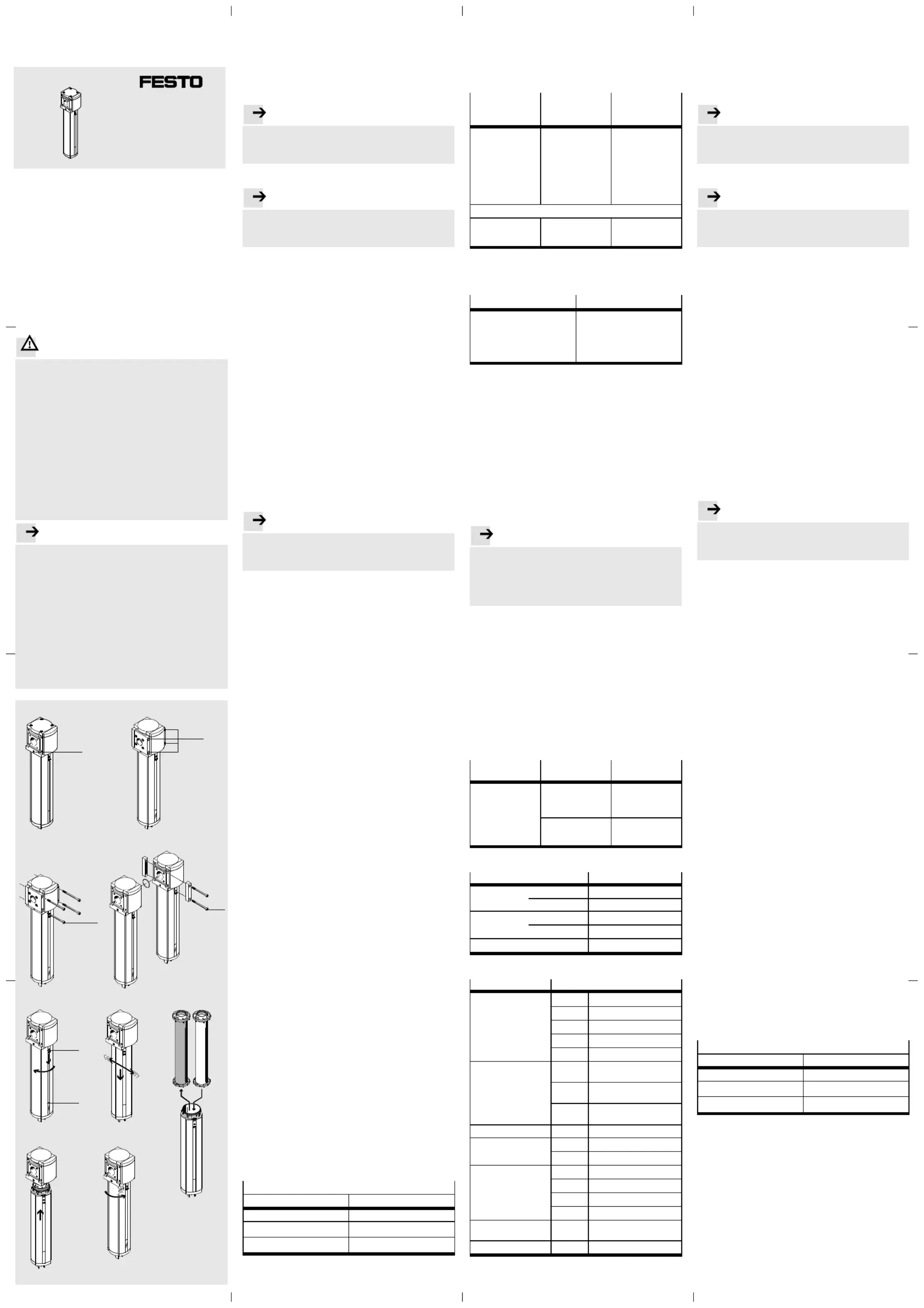
Bild1/Fig.1
1
MS9-LFM/LFX-GMS9-LFM/LFX-¾/1
Bild3/Fig.3Bild4/Fig.4
Bild5/Fig.5
Bild8/Fig.8
Bild7/Fig.7
Bild6/Fig.6
Bild9/Fig.9
2
3
4
8Nm
Bild2/Fig.2
5
6
Fein-/FeinstfilterMS9-LFMde
.................................
AktivkohlefilterMS9-LFX
1Anwendung
BestimmungsgemäßentferntderFein-/Feinstfilter
MS9-LFMSchmutzpartikelundÖltröpfchen,derAktiv-
kohlefilterMS9-LFXgasförmigeÖlbestandteileausder
durchgeleitetenDruckluft.
Hinweis
..................................................
DieGerätebenötigenfüreineneinwandfreienBetrieb
vorgefilterteDruckluftinunterschiedlicherQualität
(Betriebsmedium“TechnischeDaten”).
2VoraussetzungenfürdenProdukteinsatz
Hinweis
..................................................
DurchunsachgemäßeHandhabungentstehenFehl-
funktionen.StellenSiesicher,dassdienachfolgenden
Vorgabenstetseingehaltenwerden.
•VergleichenSiedieGrenzwerteindieserBedienungs-
anleitungmitdenenIhresEinsatzfalls(z.B.Betriebs-
medium,Drücke,Kräfte,Temperaturen,Massen,
Durchflüsse).
•BerücksichtigenSiedieVorschriftenderBerufsgenos-
senschaft,desTechnischenÜberwachungsvereinsoder
entsprechendenationaleBestimmungen.
•BerücksichtigenSiedieUmgebungsbedingungenam
Einsatzort.
•EntfernenSiedieTransportvorkehrungenwieSchutz-
wachs,Folien(Polyamid),Kappen(Polyethylen),Karto-
nagen(außerdenVerschlusselementenderpneumati-
schenAnschlüsse).
•VerwendenSiedasProduktimOriginalzustandohne
jeglicheeigenmächtigeVeränderung.
•EntfernenSiePartikelindenZuleitungenmittelsDurch-
blasenderRohreundSchläuche.DadurchschützenSie
dasGerätvorfrühzeitigemAusfalloderhöherem
Verschleiß(sieheDINISO4414,Abs.9.4).
•SorgenSiefürDruckluftmitordnungsgemäßerAufbe-
reitung.
3Einbau
3.1Mechanisch
Hinweis
..................................................
InformationenzurMontagevonModulverbinder,
AnschlussplatteundBefestigungswinkelfindenSiein
derdemZubehörbeigefügtenBedienungsanleitung.
•BeachtenSiedieDurchflussrichtungvon1nach2.
AlsOrientierungdienendieZiffern1aufdemProdukt-
gehäuse(Bild1).
•PlazierenSiedasGerätmitausreichendPlatzunterhalb
derFilterschale(min.50mm).
•JustierenSiedasGerätsenkrechtstehend(_5°).
DirektmontageeinesEinzelgerätsMS9-LFM/LFX-¾
¾
¾
¾¾/1
mitBefestigungsschrauben
1.DrückenSiealleSchutzkappen2nachvorneausden
Anschlussplatten(Bild2).SchiebenSiedazueinen
schmalenGegenstanddurchdiehintereÖffnungder
Anschlussplatte.
2.BefestigenSiedasEinzelgerätmitvierBefestigungs-
schrauben3derGrößeM6undeinerMindestlänge
von90mm(Bild3).DerAbstandzwischendenBoh-
rungenbeträgt90mminderBreiteund66mminder
Höhe.
ZusammenbaueinerFilterkombination
•BeachtenSiedieReihenfolgeentlangderDurchfluss-
richtung.
Richtigmontiert,kommtzuerstderFeinfilter
MS9-LFM-…-B(1μm),dannderFeinstfilter
MS9-LFM-…-A(0,01μm)undzuletztderAktivkohlfilter
MS9-LFX.
Zusammenbaumiteinemodermehrerenbereitsvorhan-
denenWartungsgerätendergleichenBaureihe
(Bild4)
1.DemontierenSiedenbestehendenWartungsgeräte-
strangabhängigvomgeplantenEinbauortdesGeräts
innerhalbdesStrangs.
BeiEinbauamAnfangoderEndedesWartungsgeräte-
strangs:
–DruckluftleitungamWartungsgerätestrang
demontierenoder
–AnschlussplatteamWartungsgerätestrang
demontieren.
BeiEinbauzwischenzweiWartungsgerätendes
Wartungsgerätestrangs:
–ModulverbinderMS9-MV4zwischendenbeiden
WartungsgerätendurchLösenderSchrauben
entfernen.
2.PlatzierenSiedasGerätandengewünschtenEinbau-
ort.
3.PlatzierenSiedieModulverbinderMS9-MV4inden
NutenvonMS9-LFM/LFXundbenachbartemWar-
tungsgerät.DabeiistzwischendenWartungsgeräten
eineDichtungerforderlich.
4.BefestigenSiedieModulverbinderMS9-MVmitzwei
Schrauben.
5.MontierenSiedieentferntenTeileundGeräteaus
Schritt1wiederzueinemWartungsgerätestrang
zusammen.
3.2Pneumatisch
BeiVerwendungvonAnschlussverschraubungen:
•BeachtenSiedieEinschraubtiefederAnschluss-
gewinde.
Max.Einschraubtiefe[mm]
ISO228NPT
MS9-…-¾/1:18,5MS9-…-N¾/N1:18,5
MS9-…-AGD/AGE/AGF:18,518,5MS9-…-AQR/AQS/AQT:
MS9-…-AGG/AGH:31,531,5MS9-…-AQU/AQV:
•DrehenSiedieVerschraubungenindiepneumatischen
AnschlüsseunterVerwendungvongeeignetemDicht-
material.
4WartungundPflege
AblassdesKondensats
BeiKondensatpegelhöheanderMarkierung6
(Bild5):
Manueller
Ablass
MS9-LFM-…M
Halbautomati-
scherAblass
MS9-LFM-…H
Vollautomati-
scherAblass
MS9-LFM-…V
Ablass-Schraube
(vonuntengesehen)
gegendenUhrzeiger-
sinnaufdrehen.
–Filterkurzzeitig
entlüften
(p1=0bar)
oder
–Ablass-Schraube
(vonuntengese-
hen)gegenden
Uhrzeigersinnauf-
drehen.
Filterentleert
selbständig.
ManuelleEntleerung:
Ablass-Schraube
(vonuntengesehen)
gegendenUhrzeiger-
sinnaufdrehen.
DadurchfließtdasKondensatab.
Stecknippelan-
schlussfürSchlauch
PCN-4-NTvorhanden.
QS-Anschlussfür
SchlauchPUN-6/
PAN-6vorhanden.
Stecknippelan-
schlussfürSchlauch
PCN-4-NTvorhanden.
WechselderFilterpatrone
•WechselnSiedieFilterpatronebeifolgendenAnzei-
chen:
MS9-LFM
MS9-LFX
DruckabfallΔpgrößer0,35bar.
NurMS9-LFM-…-DA:
DieroteFarbzonefülltdensicht-
barenBereichderDifferenz-
druckanzeigevollständigaus.
Wechselalle1000Betriebsstun-
denempfohlen
1.EntlüftenSiedasGerät.
2.SchiebenSiedenEntriegelungsschieber5inPfeilrich-
tung(Bild5).
3.DrehenSiedieFilterschalevonHandoderamSechs-
kantgegendenUhrzeigersinn(vonuntengesehen)bis
zumspürbarenAnschlag.
4.ZiehenSiemitvorsichtigenBewegungennachvorne
undnachhintendieFilterschalevomGerätweg
(Bild6).DadurchlöstsichgleichzeitigdieFilterpa-
troneundkanngemeinsammitderFilterschaleentfernt
werden.
5.EntnehmenSiedieFilterpatronemitzugesetztenPoren
ausderFilterschale(Bild7).
6.PlatzierenSiedieneueFilterpatroneinderFilterschale.
Hinweis
..................................................
VerhindernSiebeimWechselderFilterpatrone,dass
SchmutzpartikelindasGerätgelangen.ErgreifenSie
dieneueFilterpatronenuranderoberenundunteren
Endkappe.FüreineleichtereMontageempfiehltes
sich,denO-RinginderoberenEndkappeleichtzuölen.
7.MontierenSiedieEinzelteilewiederinumgekehrter
Reihenfolge.DabeigeltenfolgendeKontrollpunkte:
–DieNaseamEntriegelungsschieberderFilterschale
weistaufdieAussparungamGehäuse(Bild8).
–DerEntriegelungsschieberrastetbeiErreichendes
Endanschlagsdeutlichhörbarein(Bild9).
8.NehmenSiedieAnlagewiederinBetrieb.
Reinigung
•ReinigenSiebeiBedarfdasGerätmiteinemweichen
Lappenvonaußen.
ZulässigeReinigungsmediensindSeifenlauge
(max.+60°C)oderWaschbenzin(aromatenfrei).
5Störungsbeseitigung
Störung
Mögliche
Ursache
Abhilfe
GeringerDurchfluss
(beiLuftverbrauch
brichtder
Betriebsdruck
zusammen)
Filterpatroneistver-
schmutzt
Filterpatronewech-
seln(sieheKapitel
“Wartungund
Pflege”)
Verengungzwischen
Absperrventilund
Wartungseinheit
Leitungkontrollieren
6Zubehör
Bezeichnung
Typ
Feinstfilter-
patrone
StandardMS9-LFM-A
HoherDurchflussMS9-LFM-A-HF
Feinfilterpatrone
StandardMS9-LFM-B
HoherDurchflussMS9-LFM-B-HF
Aktivkohle-FilterpatroneMS9-LFX
7TechnischeDaten
TypMS9-
Eingangsdruck[bar]
LFM-…M0…20
LFM-…H1,5…12
LFM-…V2,0…12
LFM-…E…0,8…16
LFX0…20
Betriebsmedium
LFM-…-Bgefilterte,nichtgeölteDruck-
luft,Filterfeinheit5μm
LFM-…-Agefilterte,nichtgeölteDruck-
luft,Filterfeinheit1μm
LFXgefilterte,nichtgeölteDruck-
luft,Filterfeinheit0,01μm
EinbaulageLFM/LFXsenkrecht_5°
Filterfeinheit[μm]
LFM-…-B1
LFM-…-A0,01
Umgebungstemperatur/
Mediumstemperatur[°C]
LFM-…M–10…+60
LFM-…H+5…+60
LFM-…V+5…+60
LFM-…E…+1…+60
Umgebungstemperatur
[°C]
LFX–10…+60
Mediumstemperatur[°C]LFX+5…+30
Fine/microfilterMS9-LFMen
................................
ActivecarbonfilterMS9-LFX
1Application
Thefine/microfilterMS9-LFMisintendedforremoving
dirtparticlesanddropsofoil;theactivecarbonfilter
MS9-LFXisintendedforremovinggaseousoilparticles
fromthecompressedairwhichispassedthrough.
Note
......................................................
Forfaultlessoperationthedevicesrequirepre-filtered
compressedairindifferingquality(operatingmedium
“Technicalspecifications”).
2Conditionsofuse
Note
......................................................
Incorrecthandlingcanresultinmalfunctioning.Make
surethatthefollowingspecificationsarealways
observed.
•Comparethemaximumvaluesspecifiedintheseoper-
atinginstructionswithyouractualapplication(e.g.op-
eratingmedia,pressures,forces,temperatures,
masses,flowrates).
•Pleasecomplywithnationalandlocalsafetylawsand
regulations.
•Takeintoconsiderationtheambientconditionsatthe
locationofuse.
•Removealltransportpackingsuchasprotectivewax,
foils(polyamide),caps(polyethylene),cardboardboxes
(exceptforthesealingelementsofthepneumatic
connections).
•Usetheproductinitsoriginalstate.Unauthorised
modificationisnotpermitted.
•Removedirtparticlesinthesupplylinesbyblowingout
thetubingwithcompressedair.Inthiswayyouwillpro-
tectthedevicefromprematurefailureorheavywear
(seeDINISO4414,section9.4).
•Ensurethatthereisasupplyofcorrectlyprepared
compressedair.
3Fitting
3.1Mechanicalinstallation
Note
......................................................
Informationonfittingmoduleconnectors,sub-bases
andfasteningbracketscanbefoundintheoperating
instructionsenclosedwiththeaccessories.
•Notethedirectionofflowfrom1to2.
Thefigures1ontheproducthousingserveasan
orientation(fig.1).
•Placethedevicewithsufficientspacebelowthefilter
bowl(min.50mm).
•Adjustthedevicewhenitisstandingvertically(_5°).
DirectmountingofanMS9-LFM/LFX-¾
¾
¾
¾¾/1withfastening
screws
1.Pressallprotectivecaps2forwardsoutofthe
sub-base(fig.2).Inordertodothispushanarrow
objectthroughtherearopeningofthesub-base.
2.Fastentheindividualdevicewithfourfasteningscrews
3ofsizeM6andaminimumlengthof90mm
(fig.3).Thedistancebetweentheholesis90mmin
widthand66mminheight.
Fittingtogetherafiltercombination
•Notethesequnceoffiltersinthedirectionofflow.
Iffittedcorrectly,thefinefilterMS9-LFM-…-B(1μm)
comesfirst,thenthemicrofilterMS9-LFM-…-A
(0.01μm)andlasttheactivecarbonfilterMS9-LFX.
Fittingtogetherwithoneorseveralalreadymounted
serviceunitsofthesameseries(fig.4)
1.Dismantletheexistingserviceunitstringdependingon
theplannedlocationoftheMS9-LFMwithinthestring.
Ifthedeviceistobefittedatthebeginningorattheend
oftheserviceunitstring:
–disconnectthecompressedairtubingfromthe
serviceunitstringor
–removethesub-basefromtheserviceunitstring.
Ifthedeviceistobefittedbetweentwoserviceunitsin
theserviceunitstring:
–RemovethemoduleconnectorMS9-MV4between
thetwoserviceunitsbylooseningthescrews.
2.Mountthedeviceinthedesiredlocation.
3.PlacethemoduleconnectorsMS9-MV4inthegrooves
oftheMS9-LFM/LFXandtheadjoiningserviceunit.
Theremustbeasealbetweentheserviceunits.
4.FastenthemoduleconnectorsMS9-MVwithtwo
screws.
5.Fittheremovedpartsanddevicesfromstep1together
toaserviceunitstringagain.
3.2Pneumaticinstallation
Ifusingscrewconnectors:
•notethescrew-indepthoftheconnectorthreads.
max.screw-indepth[mm]
ISO228NPT
MS9-…-¾/1:18.5MS9-…-N¾/N1:18.5
MS9-…-AGD/AGE/AGF:18.518.5MS9-…-AQR/AQS/AQT:
MS9-…-AGG/AGH:31.531.5MS9-…-AQU/AQV:
•Screwtheconnectorsintothepneumaticconnections
usingasuitablesealingmaterial.
MS9-LFM/LF
X
Bedienungsanleitung
Operatinginstructions
Original:de
Festo SE & Co. KG
Postfach
D-73726Esslingen
Phone:
+49/711/347-0
www.festo.com
1112NH
8002713
Product specificaties
| Merk: | Festo |
| Categorie: | Niet gecategoriseerd |
| Model: | MS9-LFM |
Heb je hulp nodig?
Als je hulp nodig hebt met Festo MS9-LFM stel dan hieronder een vraag en andere gebruikers zullen je antwoorden
Handleiding Niet gecategoriseerd Festo

3 Mei 2026
30 April 2026
29 April 2026
29 April 2026
29 April 2026
29 April 2026
28 April 2026
28 April 2026
28 April 2026
28 April 2026
Handleiding Niet gecategoriseerd
Nieuwste handleidingen voor Niet gecategoriseerd
23 Juli 2026
23 Juli 2026
23 Juli 2026
23 Juli 2026
23 Juli 2026
23 Juli 2026
22 Juli 2026
22 Juli 2026
22 Juli 2026
22 Juli 2026