Festo CTEU-VN Handleiding
Festo
Niet gecategoriseerd
CTEU-VN
Bekijk gratis de handleiding van Festo CTEU-VN (6 pagina’s), behorend tot de categorie Niet gecategoriseerd. Deze gids werd als nuttig beoordeeld door 2 mensen en kreeg gemiddeld 3.7 sterren uit 1.5 reviews. Heb je een vraag over Festo CTEU-VN of wil je andere gebruikers van dit product iets vragen? Stel een vraag
Pagina 1/6

Translation of the original instructions
IO-Link
®
, LASAL
®
, SIGMATEK
®
, VARAN-BUS
®
are registered trademarks of the
respective trademark owners in certain countries.
1 Intended use
The bus node type CTEU-VN has been designed exclusively for use as a parti-
cipant
in VARAN-BUS networks. The bus node may only be used in its original status
without unauthorised modifications and only in perfect technical condition.
The maximum limits must not be exceeded.
The product is suitable for industrial purposes only (ClassA). Measures for inter-
ference suppression may be required in residential areas (ClassB).
Detailed information on commissioning is provided in the documentation for the
higher-order control system.
Information on VARAN-BUS:
èwww.varan-bus.net
All available documents for the product www.festo.com/pk.è
1.1 Training of qualified personnel
The product may only be commissioned by trained, qualified control and automa-
tion technology personnel, who are familiar with:
– mounting, installation, operation and diagnostics of control systems, net-
works and fieldbus systems
– applicable regulations for accident prevention and occupational safety
– the documentation for the product.
1.2 Service
Consult your local Festo repair service if you have any technical problems.
2 Safety
– Prior to assembly or installation work: switch off power supply and secure it
against being switched back on.
– For the electrical power supply, use only SELV circuits in accordance with IEC
60204-1/EN 60204-1.
– Observe the handling specifications for electrostatically sensitive devices.
– Seal unused connections with cover caps to achieve the required degree of
protection.
– Use connection hardware with the required degree of protection.
– Commission only a completely mounted and wired product.
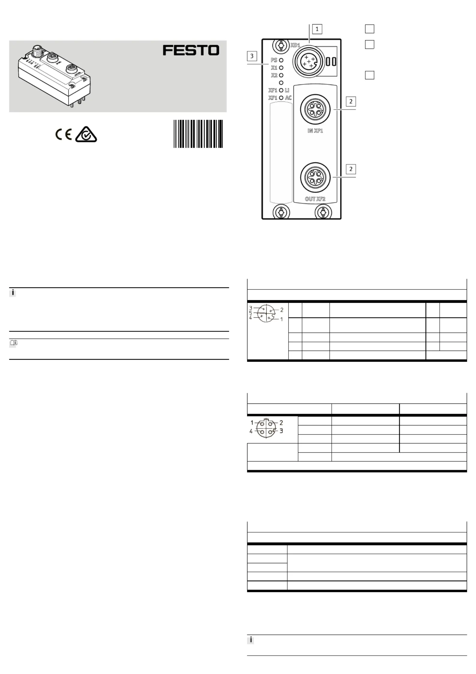
3 Connections and displays
1
Power supply connection (XD1)
è3.2 Connections
2
Network connections (network
ports IN XF1,OUT XF2, fieldbus
interface)
è3.2 Connections
3
Status LEDs
è3.3 Displays,
è7 Diagnostics via LEDs
Fig. 1
3.1 I-Port interfaces
The I-Port interfaces (X1/X2) are located on the underside of the bus node.
3.2 Connections
Power supply connection XD1
1)
Pin allocation
1 24V Operating voltage for electronics/sensors
(power system)
PS U
EL/SEN
2 24V Load voltage for valves/outputs (power
load)
PL U
VAL/OUT
3 0V Operating voltage PS U
EL/SEN
4 0V Load voltage PL U
VAL/OUT
5 FE Functional earth
2)
FE
1) plug M12, 5-pin, A-coded
2) Secure connection to functional earth over the connected product Equipotential bondingè
Tab. 1
Network connections
1)
Pin allocation IN XF1
2)
OUT XF2
2)
1 TX+ RX+
2 RX+ TX+
3 TX– RX–
4 RX– TX–
Housing (Shield/functional earth)
3)
TX = transmitted data, RX = received data
1)
2 sockets M12, 4-pin, D-coded Observe installation guidelines and line specificationsè
2) Pin allocation with deactivated crossover detection
3) Secure connection to functional earth over the connected product Equipotential bondingè
Tab. 2
3.3 Displays
Status LEDs
Meaning
PS Status of operating and load voltage supplies
X1
X2
System status "I-Port Device 1" or "I-Port Device 2"
1)
XF1 LI Connection status IN XF1 ("Link")
2)
XF1 AC Data reception IN XF1 ("Active")
1) Accessories with two I-port interfaces required to connect two products, e.g. the decentralised electric sub-
base CAPC.
2) VARAN-BUS-Status. When using the Festo Field Device Tools (FFT), e.g. for a firmware update: Ethernet
status.
Tab. 3
Additional information 7 Diagnostics via LEDs.è
8094069
CTEU-VN
Bus node
8094069
2018-10
[8094071]
Instructions| Operating| Bus node| VARAN-BUS
Festo SE & Co. KG
Ruiter Straße 82
73734 Esslingen
Germany
+49 711 347-0
www.festo.com

4 Mounting, disassembly, installation
4.1 Mounting the bus node
To mount the bus node, a product with I-Port interface is required (“I-Port
device”), e.g. a valve terminal with I-Port interface or the decentralised electrical
sub-base CAPC.
Mounting of the bus node on the decentralised electrical sub-base CAPCè
assembly instructions.
1. Switch off the power supply and secure it against being switched on again.
2. Check seal and sealing surfaces of the bus node and the product with the I-
Port interface. Replace damaged parts.
3. Push the bus node onto the product carefully and without tilting and press up
to the stop.
4. Gently tighten down the self-tapping screws, using existing threads.
5. Tighten the screws. Tightening torque: 0.7 Nm ± 10%.
4.2 Dismantling the bus node
1. Switch off the power supply and secure it against being switched on again.
2. Unscrew the screws.
3. Pull the bus node off without tilting it.
4.3 Connecting the power supply
WARNING!
Risk of injury due to electric shock.
• For the electric power supply, use only SELV circuits that guarantee a reliable
electric disconnection from the mains network.
• Observe IEC 60204-1/EN 60204-1.
• Always connect all circuits for operating and load voltage supply.
Fuse protection
The bus node supplies operating and load voltage to the connected products via
the I-Port interfaces X1 and X2.
– Protect operating voltage U
EL/SEN
and load voltage U
VAL/OUT
separately.
– Take into account the current consumption of connected products during
design and protection of the power supply.
– Observe power rating of the power supply (no bus node-internal overload
protection for the connected products) 12 Technical data.è
– Ensure correct polarity (no bus node-internal reverse polarity protection for
the connected products).
Equipotential bonding (earthing measures)
– Connect the functional earth (FE) connections of the products connected via
X1 and X2 to the earth potential with a short conductor with the greatest pos-
sible cross section ( 4 mm³
2
Cu).
4.4 Checking the power supply
Functional test:
•
The LED lights up when operating voltage is applied (within permittedPS
range).
•
The LED or lights up green if a product with an I-Port interface is con-X1 X2
nected correctly 7 Diagnostics via LEDs.è
4.5 Connecting to the network
Installation guidelines
NOTICE!
Data transmission faults
Malfunction
If installation has not been carried out correctly and high transmission rates are
used, data transmission errors may occur, e.g. as a result of signal reflections and
attenuations.
• Observe connection and line specification
• Connect screening to all network cables
• Wherever possible, only ground screening once (star-shaped) to prevent
ground loops
• Observe installation guidelines for the VARAN-BUSuser organisation (VNO):
• Observe documentation on the control system
Use of crossover cables
No restriction when using patch cables and crossover cables in the same network.
Cable specification
Cable Ethernet twisted pair cable, shielded (Shielded Twisted Pair,
STP)
Transmission class (Link Class) Category 5
Cable diameter
1)
6 ... 8 mm
Wire cross section 0.14 ... 0.75 mm
2
; 22 AWG required for max. connection
length between network participants (end-to-end link)
Connection length
2)
max. 100 m end-to-end link
1) when using the plug NECU-M-S-D12G4-C2-ET
2) corresponding to specification for VARAN-BUS networks (VARAN-BUS installation guideline)
èwww.varan bus.net‑
Tab. 4
Strain relief
When mounting on a moving part of a machine:
– Provide the network cable with strain relief.
4.6 Ensuring the degree of protection
NOTICE!
Short circuit as a result of ingress of liquids or foreign matter
Malfunction or damage to the electronics.
• Use connection devices (connecting cables, plugs, adapters) with the
required degree of protection, e.g. plug NECU-M-S-D12G4-C2-ET.
• Use cover caps to seal unused connections, e.g. cover cap ISK-M12
•
Do remove sealing plug from underside of bus node.not
• Only when mounting the bus node on the decentralised electrical sub-base
CAPC: replace sealing plug on underside of the bus node with the moulded
seal provided.
5 Commissioning, configuration and parameterisation
èDocumentation on the control system
èInformation on the VARAN-BUS user organisation
Commissioning, configuration and parameterisation of the bus node depends on
the higher-order control system. The basic approach is explained in examples in
the following sections.
5.1 Switching on the power supply
WARNING!
Uncontrolled movements of the actuators and loose tubing lines, undefined
switching states of the electronics.
Injury caused by moving parts.
• Before commissioning, ensure that the connected products do not perform
any uncontrolled movements.
• Observe commissioning notices in the control system documentation.
No automatic checking of configuration and parameterisation: the bus node and
the connected products also go into operation if configuration is incorrect.
If the control system and network participants have separate power supplies, the
following sequence is recommended for switch-on:
1. Switch on the power supply to all network participants.
2. Switch on power supply to control system.
5.2 Integrating and configuring the bus node as a network participant
5.2.1 Bus node-specific LASAL Class ("LASALClass")
Requirement:
Use of a control system from SIGMATEK and the associated controller software.
The integration of the bus node into the control system from SIGMATEK is carried
out with a bus node-specific LASAL Class, which is added using a LASAL Class file.
The integration of this file can be carried out using a graphical user interface. The
LASAL Class file (configuration file) contains all the configuration data for commu-
nication with the bus node. Further configuration of the bus node is not required.
5.2.2 VARAN Client Configuration
Example with controller software LASALCLASS from SIGMATEK:
1. Connect bus node to the control system:
2. Check the network communication between the control system and the bus
node 5.3 Checking the network communication.è
3. Start the controller software.
4. Create a new project or open an existing one.
5. In the "Graphical Hardware Editor" window, open the "Product Catalogue".
An overview of the available products opens.
6. Drag and drop the symbol for the control system and, if applicable, other
components from the "Product Catalogue" and drop it into the main window.
7. Open the directory "VARAN", sub-directory "Special".
8. Drag the "FestoCTEU-VN" symbol into the main window.
The selected components are shown with the available connection and dis-
play elements as symbols Continue from Point13.è
If the symbol "FestoCTEU-VN" is not available, continue from Point9.è
9. Activate the "Class View" window in the main menu and open it.
10. Add LASAL Class ("LASALClass") "cteu_vn" using the menu function
"Import Class/Network".
11. Close the project and re-open it.
The symbol "FestoCTEU-VN" will be available in the "Product Catalogue".
12. Drag the symbol "FestoCTEU-VN" into the main window.
13. In the "Graphical Hardware Editor" window, connect the network connections
of all components with one another:
Using the left mouse button, click on the corresponding symbol; keep the
mouse button pressed and drag the symbol to the destination.
A green line between the components indicates a successful connection.
The bus node is integrated into the VARAN-BUS network.
14. Activate the window "Network View" in the main menu and open it.
15. Open the window "HW_Network":
In the window "Network View", double click "HW_Network".
The software-based inputs/outputs (connection points) and logic elements
and their connections are shown as symbols.
16. Open the window "Class View".

17. Create new LASAL Class under "Task Settings":
Click on the root node with the right mouse button and in the context menu,
select "Create Class".
18. Give the LASAL Class a name, e.g. "ClassCTEU_VN".
19. Switch on "Properties Window".
20. In the "Properties" window under "Task Settings", configure the following
characteristics of the LASAL Class:
– "CyclicTask“: true
– "DefaultCyclic": 10 ms
21. Create client for the new LASAL Class:
Using the right mouse button, click LASAL Class and select "New Client" in
the context menu.
22. Give the client a name, e.g. "ClientCTEU_VN".
23. In the "Properties" window, configure the following characteristics of the cli-
ent:
– Type: "ObjectChannel"
– Class: "cteu_vn"
24. Create the variable for the new LASAL Class:
Using the right mouse button, click on the LASAL Class and select "New Vari-
able" in the context menu.
25. Give the variable a name, e.g.. "inputs".
26. Select the following characteristic of the variables:
– Type "cteu_vn::t_cteu_vn_Inputs"
27. Create another variable for the new LASAL Class:
Using the right mouse button again, click on the LASAL Class and select "New
Variable" in the context menu.
28. Give the variable a name, e.g. "outputs".
29. Select the following characteristic of the variables:
– Type "cteu_vn::t_cteu_vn_Outputs"
30. Add the newly created LASAL Class to the network:
Drag the LASAL Class "ClassCTEU_VN" out of the window "Class View" and
drop it into the window "HW_Network".
31. In the window "HW_Network", connect the LASAL Class with the bus node:
Using the left mouse button, click on the connection point "ClientCTEU_VN"
of the LASAL-Class, keep the mouse button pressed and drag it to the destin-
ation, the connection point "State" (Server) of the bus node
("ClassCTEU_VN").
Ä
– The bus node can be controlled via the created LASAL Class.
– The programming interface, the software API of the bus node, is
available through the associated client.
– Input/output data can be transmitted via the software API.
5.2.3 Functional test (programming example "Transferring input/output
data")
1. In the window "ClassView", double click the created LASAL Class.
The editor window opens.
2. Add instruction to transmit input/output data to the function
"ClassCTEU_VN::CyWork" (programming example):
outputs[0] := 16#aa;
outputs[1] := 16#aa;
outputs[2] := 16#aa;
outputs[3] := 16#aa;
inputs[0] := 16#aa;
inputs[1] := 16#aa;
inputs[2] := 16#aa;
inputs[3] := 16#aa;
ClientCTEU_VN.SetOutputs(Port:=cteu_vn::Port0, Value:=#outputs);
ClientCTEU_VN.GetInputs(Port:=cteu_vn::Port0, Value:=#inputs);
3. Create an online connection with the control system, compile project, down-
load and start:
Click button "Build Changes, Online, Download and Run".
4. Check the transmission of the input/output data (value change) in the control
system.
5.3 Checking the network communication
Functional test:
With a fault-free communication between control system and bus node:
•
The lights up green.LED XF1 LI
•
The flashes green.LED XF1 AC
Further information on diagnostics via LEDs 7 Diagnostics via LEDs.è
6 Payloads
Input/output addresses, parameters and other product-specific data of the bus
node are defined in the LASAL Class as a "Payload".
For the communication between the control system and the bus node, an applica-
tion programme is required Documentation on the control system.è
6.1 Input and output addresses
The input/output addresses of the bus node are defined in the configuration file
under "VARAN Address Offset (Read/Write)" 6.2 Process data ("I/O Data").è
The input/output addresses cannot be changed. The PLC specifies the respective
start addresses.
6.2 Process data ("I/O Data")
Process data (input/output data) are transmitted via the Triple Buffer. For the
reading and writing of the process data, the same I/O address is used Tableè
"I/O Addresses".
Initialisation of the process data transmission
1. Find the output data length of the I-Port devices from the device information
or the device parameters.
2. Write the value of the start address 16#0008 to the start address 16#4004
èCTEU-VN Triple Buffer Offset Read (Input Data).
3. Write the following total value to the start address 16#4006:
Value of the start address 16#0008 plus output data lengths of the I-Port
devices minus 1 CTEU-VN Triple Buffer Offset Write (Output Data).è
Transmission of input data
– Read data from the above-mentioned start address 16#4004: the bus node
transits the input data for as long as data is being read from this start
address.
Transmission of output data
– Write data to the above-mentioned start address 16#4006: the bus node
transmits and updates the output data after the last byte has been written.
I/O addresses
1)
Start address (Off-
set)
Data field size
VARAN Address Offsets
CTEU-VN Parameter Buffer Read:
I-Port 1/I-Port 2, Parameters and Dia-
gnostics
16#0000
CTEU-VN Parameter Buffer Write:
I-Port 1/I-Port 2, Parameters and Dia-
gnostics
16#0100
è 6.3 Parameters and
diagnostic information
I-Port 1, Device Information (Read) 16#0200
I-Port 2, Device Information (Read) 16#0400
è 6.4 Device information
(participant
characteristics)
CTEU-VN I/O Triple Buffer
2)
16#4000 2 Bytes
CTEU-VN Triple Buffer Offset Read (Input
Data)
16#4004 2 Bytes
CTEU-VN Triple Buffer Offset Write (Out-
put Data)
16#4006 2 Bytes
Triple Buffer Offsets
CTEU-VN Triple Buffer I/O Data Read
(Input Data)
3)
64 Bytes
CTEU-VN Triple Buffer I/O Data Write
(Output Data)
3)
16#4008
64 Bytes
CTEU-VN Triple Buffer Offset Read CTEU-VN Triple Buffer I/O
Data
2 Bytes
CTEU-VN Triple Buffer Offset Write CTEU-VN Triple Buffer I/O
Data + Output Data Length
– 1
2 Bytes
1) The specified start addresses refer to the basic address stipulated by the PLC.
2) Process data (I/O data) are transmitted via the Triple Buffer.
3) The same I/O address is used for the reading and writing of process data.
Tab. 5
6.3 Parameters and diagnostic information
The parameters and diagnostic information of the bus node are defined in the
configuration file under "CTEU-VN Input/Output Parameters" 6 Payloads.è
The memory areas for parameters and diagnostic information are sub-divided into
a read and write area. The read area reproduces the current values of the bus
node, while the values can be changed correspondingly via the write area. An ini-
tialisation of the memory areas is not required.
I/O addresses
1)
Start address
(Offset)
Data field
size
Read area
I-Port 1 – I-Port Device Parameter 16#0000 8 Bytes
I-Port 1 – IO-Link Mode
2)
16#0008 1 Bytes
I-Port 2 – I-Port Device Parameter 16#0009 8 Bytes
I-Port 2 – IO-Link Mode
2)
16#0011 1 Bytes
I-Port 1 – Diagnostics 16#0012 2 Bytes
I-Port 2 – Diagnostics 16#0014 2 Bytes
Output Failsafe Mode
3)
16#001E 1 Bytes
Write area
I-Port 1 – I-Port Device Parameter 16#0100 8 Bytes
I-Port 1 – IO-Link Mode
2)
16#0108 1 Bytes
I-Port 2 – I-Port Device Parameter 16#0109 8 Bytes
I-Port 2 – IO-Link Mode
2)
16#0111 1 Bytes
Output Failsafe Mode
3)
16#011E 1 Bytes
1) The specified start addresses refer to the basic address stipulated by the PLC.
2) IO-Link compatibility mode: no full support of the IO-Link functionality; "0" = "I-Port Mode", "1" = "IO-
Link Mode".
3) Set "Output Failsafe Mode" to "0": outputs are set to zero ("Reset Outputs"); set "Output Failsafe Mode"
to "1": the last state of the outputs is retained ("Hold Last State").
Tab. 6
Product specificaties
Merk: | Festo |
Categorie: | Niet gecategoriseerd |
Model: | CTEU-VN |
Heb je hulp nodig?
Als je hulp nodig hebt met Festo CTEU-VN stel dan hieronder een vraag en andere gebruikers zullen je antwoorden
Handleiding Niet gecategoriseerd Festo
2 Augustus 2025
2 Augustus 2025
1 Augustus 2025
1 Augustus 2025
1 Augustus 2025
1 Augustus 2025
1 Augustus 2025
1 Augustus 2025
1 Augustus 2025
1 Augustus 2025
Handleiding Niet gecategoriseerd
- CaterRacks
- Denver
- Metapen
- GMW
- Robens
- Elac
- Onlili
- Xlyne
- Renogy
- SatKing
- Furrion
- Celexon
- Cocraft
- Hedbox
- KeepOut
Nieuwste handleidingen voor Niet gecategoriseerd
13 September 2025
13 September 2025
13 September 2025
13 September 2025
13 September 2025
13 September 2025
13 September 2025
13 September 2025
13 September 2025
13 September 2025