Festo CPX-FB23-24 Handleiding
Festo
Niet gecategoriseerd
CPX-FB23-24
Bekijk gratis de handleiding van Festo CPX-FB23-24 (4 pagina’s), behorend tot de categorie Niet gecategoriseerd. Deze gids werd als nuttig beoordeeld door 2 mensen en kreeg gemiddeld 4.5 sterren uit 1.5 reviews. Heb je een vraag over Festo CPX-FB23-24 of wil je andere gebruikers van dit product iets vragen? Stel een vraag
Pagina 1/4

Bus node
CPX-FB23, CPX-FB23-24
Festo SE & Co. KG
Ruiter Straße 82
73734 Esslingen
Germany
+49 711 347-0
www.festo.com
Brief description
Translation of the original instructions
8101635
2018-11c
[8101637]
Bus node CPX-FB23, CPX-FB23-24 English. . . . . . . . . . . . . . . . . . . . . . . . . . . . . . . .
For all available product documentation è www.festo.com/pk
1 Intended use
The bus node type is intended exclusively for use as a participant on a CC-Link
fieldbus for CPX terminals.
The specified limits for technical data must be adhered to. You can find detailed
information in the bus node description P.BE-CPX-FB23-24 and in the CPX system
description P.BE-CPX-SYS-…
Note
This description refers to the bus nodes
– CPX-FB23 from revision R14 (CC-Link Version 1.1) and
– CPX-FB23-24 from revision R22 (CC-Link Version 1.1 and 2.0).
The bus node CPX-FB23-24 can be configured as function module F24 (CC-Link
Version 2.0) or as function module F23 (CC-Link Version 1.1).
– Generally valid information is described on this page.
– Commissioning with configuration as function module F24 or F23 is described
on the reverse side.
The bus node is intended for use in an industrial environment. Outside of indus
trial environments, e.g. in commercial and mixed-residential areas, actions to
suppress interference may have to be taken.
Only commission a CPX terminal which has been completely mounted and
connected.
CC-Link
®
, LEONI
®
and TORX
®
are registered trademarks of the respective
trademark owners in certain countries.
Note
The bus node includes electrostatically sensitive devices.
Do not touch any components.
Observe the handling specifications for electrostatically sensitive
devices.
Warning
Electric shock
Injury to people, damage to the machine and system
Use for the electrical power supply only PELV circuits in accordance with
IEC 60204-1 (Protective Extra-Low Voltage, PELV).
Observe the general requirements in accordance with IEC 60204-1 for PELV
circuits.
Use only voltage sources that guarantee a reliable electric disconnection of
operating and load voltage in accordance with IEC 60204-1.
Always connect all circuits for operating and load voltage supplies U
EL/SEN
,
U
VAL
and U
OUT
.
Connect the earth terminal of the end plates of the CPX terminal with low
resistance and impedance (short cable with the largest possible cross sec
tion) to the earth potential.
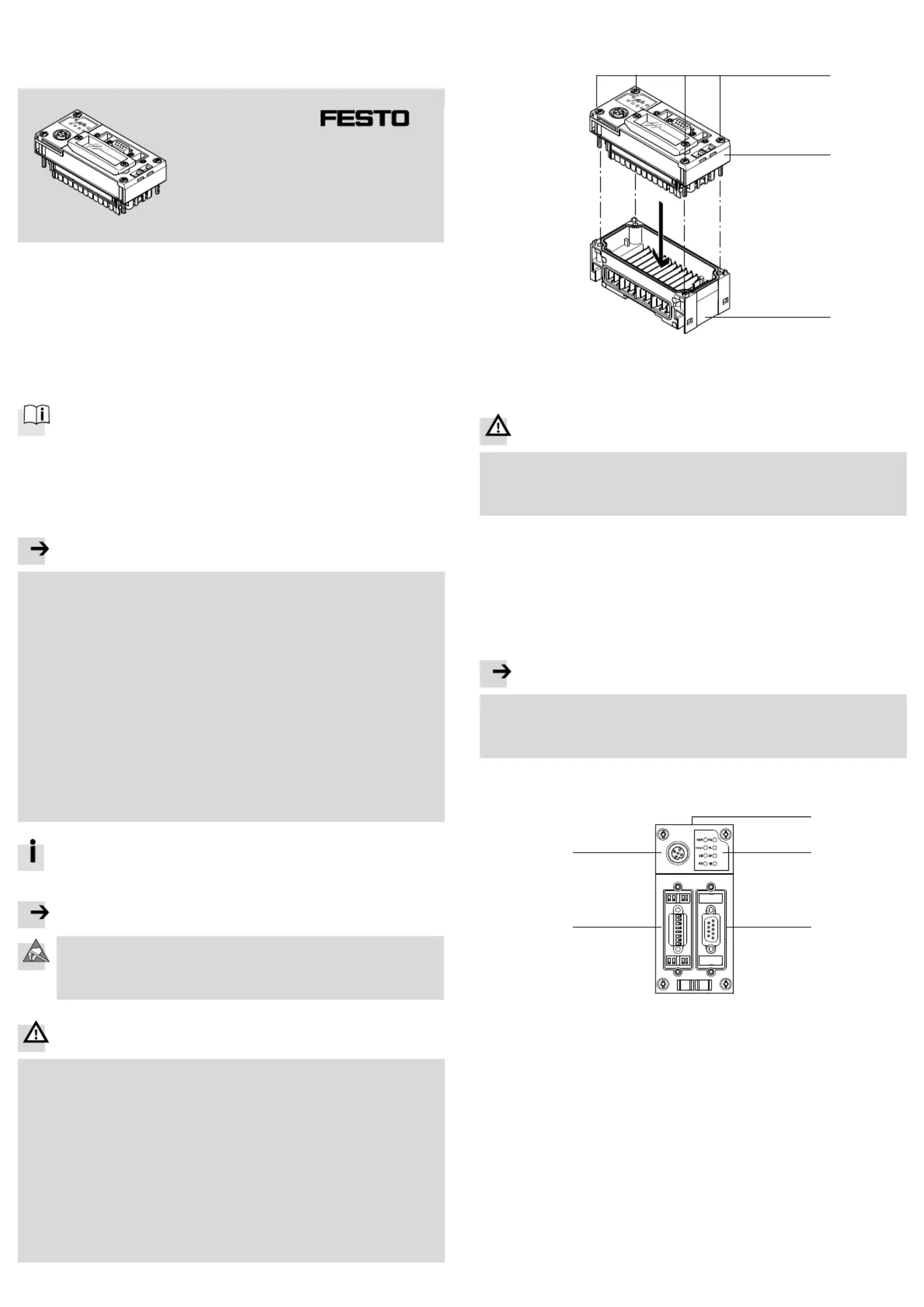
2 Mounting/dismounting
When built-in, the bus node is located in an interlinking block of the CPX terminal.
1
2
3
1TORX
®
T10 screws
2Bus nodes
3Interlinking block with contact rails
Fig. 1
Warning
Electric shock
Injury to people, damage to the machine and system
Switch off the power supply before assembling or disassembling bus nodes
(risk of operative malfunction or damage).
Dismounting:
Unscrew screws and carefully lift off the bus node.
Mounting:
1. Check seal and seal surfaces.
2. Carefully insert manifold block into the interlinking block and press it in.
3. Screws must be set so that the existing threads can be used. Tighten the
screws by hand in diagonally opposite sequence.
Tightening torque: 0.9 … 1.1 Nm.
Note
Use appropriate screws, dependent on the material of the interlocking block
(metal or plastic):
–Plastic interlinking block: thread-cutting tapping screws
–Metal interlinking block: screws with metric thread.
3 Connection and display components
1
2
34
5
1Rating plate
2Fieldbus- and CPX-specific LEDs
3Fieldbus connection
1)
4Cover for DIL switches
5Service interface for
operator unit (CPX-MMI) or Festo
Maintenance Tool (CPX-FMT)
2)
1) Connection: Sub-D socket, 9 pin 2) Connection: M12 socket, 5 pin
Fig. 1

3.1 LED display component - standard operating status
Characteristics of the LED display components in standard operating status:
– All green LEDs are illuminated (Run, PS and PL).
– The yellow LEDs light up or flash, dependent on the data communication or
configuration (SD, RD and M).
– The red LEDs do not light up (error, SF).
CC-Link-specific LEDs CPX-specific LEDs
2)
Run (green) Data communication OK
1)
PS (green) Power system
Error (red) Data communication faulty
1)
PL (green) Power load
SD (yellow) Send data SF (red) System failure
3)
RD (yellow) Receive data M (yellow) Modify
4)
1) Detailed information è Bus node description P.BE-CPX-FB23-24
2) Detailed information è CPX system description P.BE-CPX-SYS-…
3) Flashes in case of error, error diagnostics è CPX system description P.BE-CPX-SYS-…
4) Parameterisation revised or “Force” active.
Fig. 2
3.2 Pin allocation and specification of the fieldbus interface
Connection Pin Signal Explanation
Sub-D socket, 9-pin
2
3
7
Housing
DA
DG
DB
SLD/FG
Data A
Data reference potential (data ground)
Data B
Screening/functional earth (shield/functional
earth, here designated as functional ground)
Fig. 3
Connection technology Achievable degree of protection
Festo plug connector FBS-SUB-9-GS-2x4POL-B IP65/IP67
Festo bus connection FBA-1-KL-5POL IP20
Other sub-D plug connectors
Fig. 4
Cable specification
Cable type CC-110, CC-110-5, CS-110, CM-110-5, 20 AWG x 3
1)
FANC-110SBH, 20 AWG x 3
2)
L45467-Y19-C15, 20 AWG x 3
3)
Length of cable between the participants > 0.2 m (for all baud rates)
Maximum cable length
(dependent on the baud rate)
156 kBd
625 kBd
2.5 MBd
5 MBd
10 MBd
1200 m
900 m
400 m
160 m
100 m
Terminating resistor
between pin 2 and pin 7
110 Ω _ 5 %, 0.5 W
1) DYDEN Corporation
2) KURAMO ELECTRIC Co., Ltd.
3) LEONI protec cable systems GmbH
Fig. 5
4 Parameterisation
Note
The CPX terminal and the related bus node can be parameterised by means of
the Festo operator unit (CPX-MMI) or Festo Maintenance Tool (CPX-FMT).
Further information on parameterisation, module replacement and start-
up behaviour of the CPX terminal can be found in the bus node descrip
tion P.BE-CPX-FB23-24
You can find information on the fieldbus CC-Link in the documenta
tion of your CC-Link Master and the related control system or in the
internet (è www.cc-link.org).
5 Start-up behaviour of the CPX terminal
If the Modify LED M lights up or flashes permanently after the system start, “Sys
tem start with saved parametrisation and saved CPX expansion” is set or “Force” is
active.
6 Note on module replacement
Caution
For CPX terminals with a continuously illuminated or flashing M LED, the para
meterisation is not automatically created by the higher-level system when the
CPX terminal is replaced during servicing.
Before replacement, note required settings and make them again after re
placement.
7 Power supply of the CPX terminal
The operating and load voltage supply for the CPX terminal is fed in via interlinking
blocks. These conduct the operating and load voltages to the neighbouring mod
ules (è CPX system description P.BE-CPX-SYS-…).
8 Technical data
Bus node
CPX-FB23, CPX-FB23-24
Function module F24 F23
General technical data è CPX system description P.BE-CPX-SYS-...
Degree of protection through housing
1)
completely mounted in accordance with IEC
60529, plug connector inserted or provided
with cover cap
2)
With plug connector FBS-SUB-9-GS-2X4POL-B
With bus connection FBA-1-KL-5POL or other
plug connectors for the bus connection
IP65/IP67
IP20
Protection against electric shock
Protection against direct and indirect contact in
accordance with IEC 60204-1
through the use of PELV circuits
Intrinsic current consumption bus node
from operating voltage supply for
electronics/sensors (U
EL/SEN
)
typ. 70 mA at 24 V (internal electronics)
Separation
Fieldbus connection at U
EL/SEN
Galvanically separated
Mains buffering time 10 ms
Module code (CPX-specific)
Remote I/O
Remote controller
Module identifiers (CPX-MMI, CPX-FMT)
Remote I/O
Remote controller
206
–
FB24-RIO CC-Link V2
remote I/O
–
206
157
FB23-RIO CC-Link
remote I/O
FB23-RC
Fieldbus-specific characteristics
Protocol
Version
Vendor code
Machine type
CC-Link
Version 1.1 and 2.0
0x0177
0x3C
CC-Link
Version 1.1
0x0177
0x3C
Data transmission rate (baud rate) 156 kBd
625 kBd
2.5 MBd
5 MBd
10 MBd
1) Observe that connected devices may only satisfy a lower degree of protection or a smaller temperature
range, etc.
2) Cover cap from Festo, type ISK-M12, included in the scope of delivery
Fig. 6

9 Commissioning as function module F24
9.1 Setting the DIL-switches
DIL switches
Setting Function
ON
1
ON
ON ON
12 2
21 12
ON
1 2 3 4 5 6 7 8
1.1 OFF (factory setting)
ON
Operating mode: remote I/O
For F24 not possible
1.2
2.1
2.2
1.2
OFF
ON
Off
ON
OFF
2.1
OFF
OFF
ON
ON
OFF
2.2
OFF
OFF
OFF
OFF
ON
Baud rate:
156 kBd
625 kBd
2.5 MBd
5 MBd
10 MBd (factory setting)
3.8 OFF
ON (factory setting)
Function module F23
Function module F24
3.7
to
3.1
3.7:
3.6:
3.5:
3.4:
3.3:
3.2:
3.1:
2
2
x 10
2
1
x 10
2
0
x 10
2
3
2
2
2
1
2
0
= 40
= 20
= 10
= 8
= 4
= 2
= 1
CC-Link slave address
Address range: 1 … 64
Factory setting: 1
5.2 OFF (factory setting)
ON
No system diagnostics
With system diagnostics
5.1 OFF (factory setting)
ON
CLEAR
HOLD
4.2 OFF (factory setting)
ON
Mapping: cycle-time-optimised
Mapping: station-optimised
4.1 OFF (factory setting)
ON
No function
Fig. 7
9.2 Useful data volume at different mapping optimisations
The number of stations and cycles required is automatically determined by the bus
node corresponding to the selected type of optimisation (cycle-time-optimised or
station-optimised).
Assigned
stations
Transmitted data
2)
Cycle setting
Single
1)
2-fold 4-fold 8-fold
1 station Inputs in bit area
2 bytes 2 bytes 6 bytes 14 bytes
Cycle-time-optimised
Outputs in bit area
2 bytes 2 bytes 6 bytes 14 bytes
Inputs in word area
8 bytes 16 bytes 32 bytes 64 bytes
Outputs in word area
8 bytes 16 bytes 32 bytes 64 bytes
2 stations Inputs in bit area
6 bytes 10 bytes 22 bytes 46 bytes
Outputs in bit area
6 bytes 10 bytes 22 bytes 46 bytes
Inputs in word area
16 bytes 32 bytes 64 bytes 64 bytes
Outputs in word area
16 bytes 32 bytes 64 bytes 64 bytes
3 stations Inputs in bit area
10 bytes 18 bytes 38 bytes 64 bytes
Outputs in bit area
10 bytes 18 bytes 38 bytes 64 bytes
Inputs in word area
24 bytes 48 bytes 64 bytes 64 bytes
Outputs in word area
24 bytes 48 bytes 64 bytes 64 bytes
4 stations Inputs in bit area
14 bytes 54 bytes26 bytes –
Outputs in bit area
14 bytes 54 bytes26 bytes –
Inputs in word area
32 bytes 64 bytes 64 bytes –
Outputs in word area
32 bytes 64 bytes 64 bytes –
Station-optimised
1) Setting requires configuration of the bus node in the master as CC-Link 1.1 slave.
2) Digital modules (incl. valves) are mapped into the bit area; analogue and function modules are mapped
parallel to that into the word area.
Fig. 8
Emphases in table Fig. 8
– Light-grey shaded: single cycle setting requires configuration of the bus
node in the master as CC-Link 1.1 slave, otherwise communication error.
– Light-grey background: additionally limited by CPX system limit.
– Dark-grey background: configuration not possible.
Note
– The bus node automatically determines the number of inputs and outputs of
the modules installed in the CPX terminal.
– According to the set mapping optimisation (cycle-time- or station-optimised),
the cycle setting and the required number of stations is automatically con
figured.
– Depending on the required address volume, the CPX terminal occupies one or
several stations (address space) in the CC-Link system.
– For an activated system diagnostics function, the 1st word in the word area is
assigned to station 1 (16 input and 16 output addresses). If the I/O dia
gnostics interface of the system diagnostics is not used, the first 8 inputs
represent the status bits.
9.3 Addressing rules
I/O counting mode
– The address assignment of the inputs is independent of the address assign
ment of the outputs.
– The counting mode is independent of the position of the bus node in the CPX
terminal.
– Counting from left to right, corresponding to the installation position in the CPX
terminal and dependent on the module type.
– Digital I/Os, analogue I/Os and I/Os of technology modules occupy their ad
dress volume ascending respectively without gaps in the corresponding ad
dress space.
– Digital I/Os are mapped in the bit area, analogue I/Os and I/Os of technology
modules are mapped parallel in the word area, starting from the 1st station to
be mapped.
– Remote ready (RR, CC-Link-specifically reserved) always lies in the bit area at
the end in the respectively last-occupied station or last-used cycle.
The last 16 inputs and outputs (2 bytes each) in the bit range (RX, RY) of the
last assigned station are CC-Link-specifically reserved.
– The status bits and the I/O diagnostics interface of the system diagnostics
occupy, if activated, the first 2 bytes respectively of the inputs and outputs of
the word area of the 1st station.
The system diagnostics occupy the first 16 inputs and outputs (2 bytes each) in
the word range (RWr, RWw) of the 1st station.
9.4 Address assignment after extension/conversion
If the machine requirements change, the CPX terminal can be adapted as required
due to its modular design.
Caution
If the CPX terminal is extended or converted at a later stage, input/output ad
dresses may be shifted.
This applies in the following cases:
– Additional modules are inserted between existing modules.
– Existing modules are removed or replaced by other modules, which have
fewer or more input/output addresses.
– Interlinking blocks or pneumatic manifold blocks for monostable valves are
replaced by interlinking blocks/manifold blocks for bistable valves – or vice
versa.
– Additional interlinking blocks and/or manifold blocks are inserted between
existing ones.
– The configured addresses of the pneumatic interface are modified.
Product specificaties
Merk: | Festo |
Categorie: | Niet gecategoriseerd |
Model: | CPX-FB23-24 |
Heb je hulp nodig?
Als je hulp nodig hebt met Festo CPX-FB23-24 stel dan hieronder een vraag en andere gebruikers zullen je antwoorden
Handleiding Niet gecategoriseerd Festo
2 Augustus 2025
2 Augustus 2025
1 Augustus 2025
1 Augustus 2025
1 Augustus 2025
1 Augustus 2025
1 Augustus 2025
1 Augustus 2025
1 Augustus 2025
1 Augustus 2025
Handleiding Niet gecategoriseerd
- Oreck
- KONFTEL
- BabyHome
- Cosina
- Bebob
- Kwantum
- Xblitz
- AER
- Algo
- Miomare
- Intermatic
- VMV
- Edikio
- Walkstool
- MotorScrubber
Nieuwste handleidingen voor Niet gecategoriseerd
13 September 2025
13 September 2025
13 September 2025
13 September 2025
13 September 2025
13 September 2025
13 September 2025
13 September 2025
13 September 2025
13 September 2025