Festo CPX-FB14 Handleiding
Festo Niet gecategoriseerd CPX-FB14
Bekijk gratis de handleiding van Festo CPX-FB14 (3 pagina’s), behorend tot de categorie Niet gecategoriseerd. Deze gids werd als nuttig beoordeeld door 12 mensen en kreeg gemiddeld 4.4 sterren uit 7 reviews. Heb je een vraag over Festo CPX-FB14 of wil je andere gebruikers van dit product iets vragen? Stel een vraag
Pagina 1/3
CPX bus node CANopen
CPX-FB14
Festo SE & Co. KG
Ruiter Straße 82
73734 Esslingen
Germany
+49 711 347-0
www.festo.com
Brief description
Translation of the original instructions
8101627
2018-11c
[8101629]
CPX bus node CANopen CPX-FB14English................................
For all available product documentation è www.festo.com/pk
1User instructions
The bus node CPX-FB14 for CPX terminals is intended exclusively for use as a parti
cipant (Slave) in a CANopen network.
The specified limits for technical data must be adhered to. You can find detailed
information in the bus node description P.BE-CPX-FB14-... and in the CPX system
description P.BE-CPX-SYS-.…
CANopen
®
and TORX
®
are registered trademarks of the respective trademark
owners in certain countries.
Warning
Switch off the power supply before assembling or disassembling modules or
plugging plug connectors together or separating them (danger of operative
malfunctions or damage).
Only use PELV circuits in accordance with IEC/EN 60204-1 (protective extra-
low voltage, PELV) for the electrical power supply.
Observe also the general requirements for PELV power circuits in accordance
with IEC/EN 60204-1.
Only use voltage sources which guarantee reliable electrical isolation of the
operating voltage in accordance with IEC/EN 60204-1.
Connect an earth conductor of sufficient cable cross section to the connection
of the CPX terminal marked with the earth symbol.
Note
The CPX bus node contains electrostatically sensitive devices.
Therefore, do not touch any components.
Observe the handling specifications for electrostatically sensitive devices.
This will help to prevent damage to the electronics
Note
Only commission a CPX terminal which has been completely mounted and
connected.
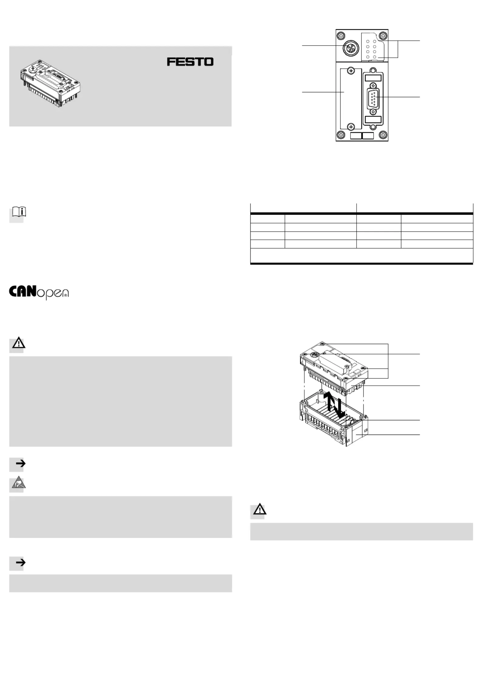
2Connection and display components
MSPS
PL
SF
M
NS
IO
51
96
1
2
4
3
1Bus-status-specific and
CPX-specific LEDs
2Fieldbus connection (9-pin Sub-D
plug)
3Cover for DIL switches
4Service interface for handheld,
etc.
Fig. 1
CANopen-specific LEDsCPX-specific LEDs
MSModule status (green/red)
1)
PSPower system (green)
1)
NSNetwork status (green/red)
1)
PLPower load (green)
1)
IOI/O status (green/red)
1)
SFSystem failure (red)
1
)
MModify (yellow)
1)
2)
1)P.BE-CPX-FB14-…Detailed information: è bus node description
2)Parameterisation revised or “Force” active
Fig. 2
Normal operating status:
The LEDs MS, NS, IO, PS and PL light up green; the LEDs SF and M do not light up.
3Installation instructions
3.1Mounting/dismounting
When built-in, the bus node is located in an interlinking block of the CPX terminal.
3
1
2
4
1TORX T10 screws; tightening
torque 0.9…1.1 Nm
2Bus node CPX-FB14
3Contact rails
4Interlinking block
Fig. 3
Warning
Switch off the power supply before assembling or disassembling bus nodes
(danger of operative malfunction or damage).
Dismantling:
Unscrew screws and carefully lift off the bus node.
Product specificaties
| Merk: | Festo |
| Categorie: | Niet gecategoriseerd |
| Model: | CPX-FB14 |
Heb je hulp nodig?
Als je hulp nodig hebt met Festo CPX-FB14 stel dan hieronder een vraag en andere gebruikers zullen je antwoorden
Handleiding Niet gecategoriseerd Festo

3 Mei 2026
30 April 2026
29 April 2026
29 April 2026
29 April 2026
29 April 2026
28 April 2026
28 April 2026
28 April 2026
28 April 2026
Handleiding Niet gecategoriseerd
Nieuwste handleidingen voor Niet gecategoriseerd
24 Juli 2026
24 Juli 2026
23 Juli 2026
23 Juli 2026
23 Juli 2026
23 Juli 2026
23 Juli 2026
23 Juli 2026
23 Juli 2026
23 Juli 2026