Festo CPX-CEC-M1-V3 Handleiding
Festo
Niet gecategoriseerd
CPX-CEC-M1-V3
Bekijk gratis de handleiding van Festo CPX-CEC-M1-V3 (3 pagina’s), behorend tot de categorie Niet gecategoriseerd. Deze gids werd als nuttig beoordeeld door 2 mensen en kreeg gemiddeld 4.0 sterren uit 1.5 reviews. Heb je een vraag over Festo CPX-CEC-M1-V3 of wil je andere gebruikers van dit product iets vragen? Stel een vraag
Pagina 1/3

Control block
CPX-CEC
Festo SE & Co. KG
Ruiter Straße 82
73734 Esslingen
Germany
+49 711 347-0
www.festo.com
Brief description
(Translation of the original instructions)
CODESYS controller
8060496
2018-05c
[8060498]
Control block CPX-CEC English
1 Use for intended purpose
The control block is intended exclusively for use in machines or automated systems.
The control block serves as CODESYS controller for:
– Controlling CPX terminals
– Controlling pneumatic and electric actuators
– Communication via Ethernet
The control block may only be used as follows:
– As intended in industrial environments. Outside of industrial environments,
e.g. in commercial and mixed-residential areas, actions to suppress interference
may have to be taken.
– In its original condition, without unauthorised modifications.
– In faultless technical condition.
– Only in combination with approved components.
– Within the limits of the product defined through the technical data.
Take the following into consideration for the destination:
– Regulations and standards
– Regulations of the testing organisations and insurers
– National specifications
Additional information:
– In the description of the control block è Fig. 1
– In the CPX system description è CPX-SYS-...
– On ModbusTCP è www.modbus.org
All available documents for the product è www.festo.com/pk.
CANopen
®
, CODESYS
®
, MODBUS
®
are registered trademarks of
the respective trademark owners in certain countries.
This product uses open-source software which is subject to the “GNU General
Public License, Version 2”. The license terms of the GPL are available within
the programming system as well as at the following addresses:
– http://www.gnu.org/copyleft/gpl.html
– Internal CPX-CEC-…-V3 web server:
http://<IP address of the device>/cgi-bin/system-about
Variants
The control block is available in the following variants:
Control block CODESYS Interface Description
CPX-CEC RS232 CPX-CEC-...V2 pbF
CPX-CEC-C1 CANopen
CPX-CEC-M1 1) CANopen + SoftMotion
CPC-CEC-S1-V3 RS232 CPX-CEC-...-V3V3 pbF
CPX-CEC-C1-V3 CANopen
CPX-CEC-M1-V3 CANopen + SoftMotion
1) Discontinued 12/2015, alternative product: CPX-CEC-M1-V3
Fig. 1 Variants of the control block
Training of qualified personnel
The product must only be commissioned by trained experts in control and automa
tion technology who are familiar with:
– Mounting, installation, operation and diagnostics of control systems, networks
and fieldbus systems.
– The applicable regulations for accident prevention and occupational safety.
– The documentation for the product.
Service
Contact your regional Festo contact person if you have technical questions
è www.festo.com.
2 Safety
Before assembly or installation work:
Switch off the power supply.
Switch off the compressed air supply.
Exhaust any pneumatic components.
Observe the instructions for correctly mounting the CPX terminal.
For the electric power supply, use only PELV circuits that ensure a reliable elec
tric disconnection from the mains network.
Observe IEC602041/EN602041.
Observe the handling specifications for electrostatically sensitive devices.
Observe the notes on installation and power supply as well as potential equal
isation (earthing measures) in the CPX system description è CPX-SYS-...
Use connectors with the required degree of protection
è Ensuring the degree of protection.
Seal unused connections with covers to achieve the required degree of protec
tion è Ensuring the degree of protection.
Observe the specifications in the CPX system description, in the descriptions of
the valve terminal used as well as in the assembly instructions of the individual
components.
Place only a completely mounted and wired CPX terminal into operation.
Only switch on the compressed air and load voltage if the system has been pro
fessionally installed, configured and parameterised.
When performing maintenance and repair work, use suitable interlocks to pre
vent unintended movements of the actuators.
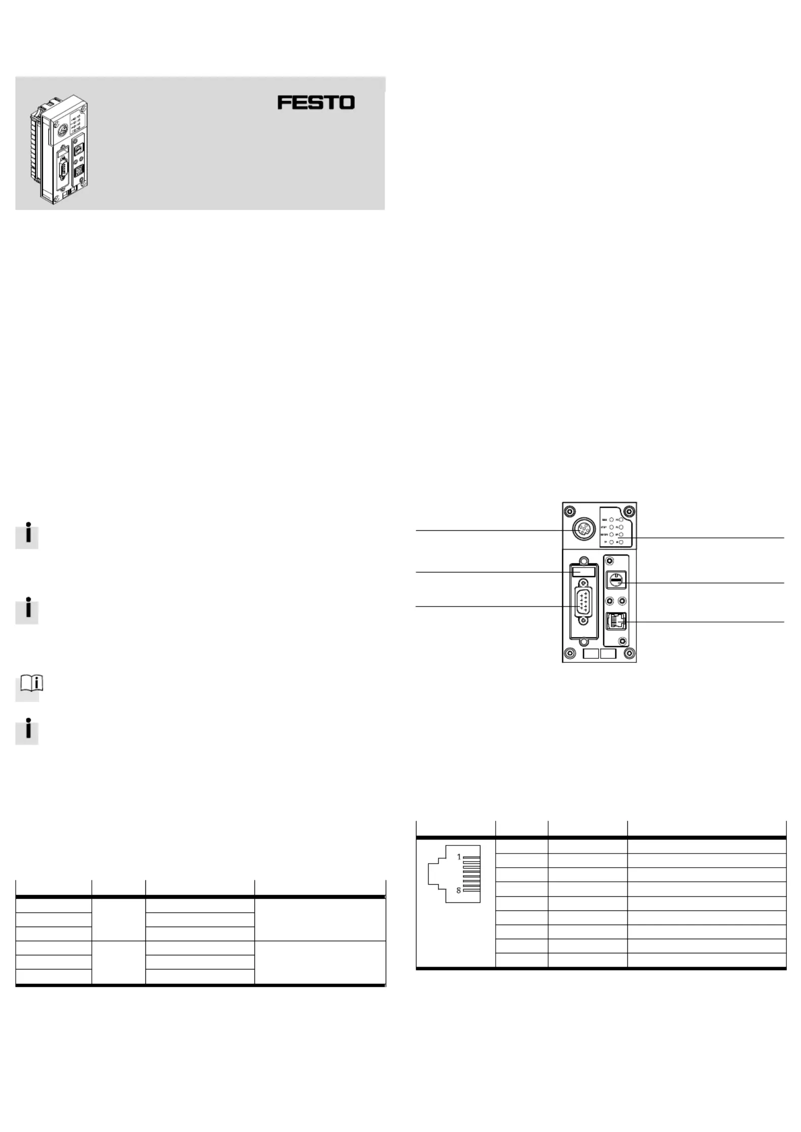
3 Connection and display components
4
1
2
3
5
6
1LED indicators
2RUN/STOP rotary switch
3Ethernet interface
4Communication interface
1)
5DIL switch
6Service interface
2)
1) For CPX-CEC-C1/M1/C1-V3/M1-V3: CANopen interface (plug, 9-pin, Sub-D),
for CPX-CEC/-S1-V3; RS232 interface (socket, 9-pin, Sub-D).
2) Socket, M12, A-coded, 5-pin; for the operator unit CPX-MMI.
Fig. 2 Connection and display components
3.1 Ethernet interface
The Ethernet interface connection of a programming unit, PC or operator unit
to the control block.
Connection Pin Signal Explanation
1 TD+ Transmitted data+
2 TD– Transmitted data-
3 RD+ Received data+
4 – Not connected
5 – Not connected
6 RD– Received data-
7 – Not connected
8 – Not connected
Housing – Shield
Fig. 3 Ethernet interface, socket, 8-pin, RJ45

3.2 CANopen interface (CPX-CEC-C1/M1/C1-V3/M1-V3)
Connection Pin Signal Explanation
51
96
1 N.c. Not connected
2 CAN_L CAN Low
3 CAN_GND CAN Ground
4 N.c Not connected
5 CAN_SHLD Functional earth
6 CAN_GND
1)
CAN Ground (optional)
1)
7 CAN_H CAN High
8 N.c. Not connected
9 N.c. Not connected
Housing (plug) – Functional earth
1) Do not use pin 6 (CAN_GND) if a motor controller with external power supply is connected.
Fig. 4 CANopen interface, plug, 9-pin, Sub-D
The connected CAN-bus slaves are not supplied with voltage through
the CANopen interface.
3.3 RS232 interface (CPX-CEC/-S1-V3)
Connection Pin Signal Explanation
1 – Not connected
2 RxD Received data
3 TxD Transmitted data
4 – Not connected
5 GND Data reference potential
6 – Not connected
7 – Not connected
8 – Not connected
9 – Not connected
Shield – Shield, functional earth
Fig. 5 RS 232 interface, socket, 9-pin, Sub-D
3.4 LED indicators – normal operating status
8
7
6
5
4
3
2
1
1PS: Electronics supply, sensor
supply (green)
2PL: Load supply (green)
3SF: System fault (red)
4M: Modify/forcing active (yellow)
5TP: Ethernet connection
link/traffic (green)
6ERROR: PLC run-time error (red)
7STOP
1)
: PLC status: stopped
(yellow)
8RUN
1)
: PLC status: started
(green)
1) The LEDs RUN8 7 and STOP display the status of the RUN/STOP rotary switch.
Fig. 6 LED indicators
Behaviour of the LED indicators in normal operating status:
– The green LEDs [PS] and [PL] are illuminated.
– The red LEDs [SF] and [ERROR] are off.
The yellow LED [M] lights up only when “System start with saved paramet
erisation and CPX configuration” is set.
4 Assembly and disassembly
Before mounting, dismounting or installation work:
Switch off the power supply.
Switch off the compressed air supply.
Exhaust any pneumatic components.
1
2
3
1Control block CPX-CEC-...
2Interlinking block
3Screws
Fig. 7 Assembly and disassembly
4.1 Assembly
For a control block with CODESYS V2:
Mount CPX-CEC/-C1/-M1 to the left end position of the CPX terminal
(position0).
1. Check seal and seal surfaces. Replace damaged parts.
2. Insert the module into the interlinking block and push it in up to the stop.
3. Turn the screws into the existing thread.
4. Tighten the screws in diagonally opposite sequence. Tightening torque:
1 Nm±10 %.
4.2 Dismantling
1. Unscrew the screws.
2. Pull the control block without tilting out of the interlinking block.
5 Power supply
Caution
Risk of injury due to electric shock
For the electric power supply, use only PELV circuits that ensure a reliable
electric disconnection from the mains network.
IEC60204-1/EN60204-1 to be screwed in.
Always connect all circuits for operating and load voltage supplies U
EL/SEN
,
U
VAL
and U
OUT
.
The operating and load voltage supplies of the CPX terminal are supplied through an
interlinking block, an end plate or a bus node è CPX system descriptionCPX-SYS-...
6 Set switch elements
6.1 RUN/STOP rotary switch
Note
The RUN/STOP rotary switch is set to position “1” at the factory.
Set the RUN/STOP rotary switch to position “0” (STOP) during installation
to prevent automatic program start after the voltage is switched on or by
commissioner.
The switch setting of the RUN/STOP rotary switch is detected by the control block
and is available in CODESYS.
To set the RUN/STOP rotary switch:
Dismount cover.
Switch setting Function
0 Stop
Control block stopped.
The STOP LED is illuminated yellow.
1 …F RUN
Control block started.
The RUN LED is illuminated green.
Fig. 8 RUN/STOP rotary switch

6.2 DIL switch 1: Reserved
Switch setting Function
DIL 1.1: OFF
DIL 1.2: OFF
Reserved
Leave both switch elements of the DIL switch 1 set
to OFF.
Fig. 9 DIL switch1
6.3 DIL switch2: CAN bus termination
To set DIL switch2:
Dismount inspection cover or pull the plug from the communication interface 4
(è Fig. 2).
Switch setting Function
1)
DIL 2.1: OFF
DIL 2.2: OFF
CAN bus termination (120 Ω) is switched off (factory setting).
DIL 2.1: ON
DIL 2.2: OFF
CAN bus termination (120 Ω) is switched on
(only for CPX-CEC-C1/M1/C1-V3/M1-V3).
DIL 2.1: OFF
DIL 2.2: ON
Reserved
DIL 2.1: ON
DIL 2.2: ON
Reserved
1) DIL switch2: no function in CPX-CEC/-S1-V3
Fig. 10 DIL switch2
7 Ensuring the degree of protection
Note
Short circuit
Malfunction or damage to the electronics.
Use connection hardware with the required degree of protection.
Seal unused connections, rotary switches and DIL switches with covers.
Mount cover
1. Check seal and seal surfaces.
2. Place cover and press it on.
3. Tighten the screws. Tightening torque: max. 0.4 Nm.
Connection/switch CoverConnection technology
Ethernet FBD plug RJ45-8-GS Cover AK-RJ45
1)
CAN bus Plug connector FBS-
SUB-9-BU-2x5POL-B
Inspection cover AK-
SUB-9/15-B
2)
RS232 Plug connector FBS-
SUB-9-GS-1x9POL-B
Service interface Connecting cable for operator unit
CPX-MM IKV-M12-M12-...
Cover cap ISK-M12
Rotary switch – Cover AK-RJ45
1)
1) Included in the scope of delivery
2) Inspection cover also for DIL switches
Fig. 11 Connectors and covers
For further information on connectors è Description of the control block,
www.festo.com/catalogue.
8 Commissioning
Information regarding commissioning è Description of the control block.
9 Notes on module replacement
Note
If the “Modify” LED (M) is continuously illuminated or flashes, parameterisation
is not automatically performed by the higher-level system when the control
block or CPX terminal is replaced during servicing.
Note the required settings before replacement, and re-establish them after
replacement.
If the “Modify” LED (M) lights up permanently or flashes after the system start,
“System start with saved parameterisation and saved CPX configuration” is set or
“Force” is active.
10 Technical data
Type CPX-CEC-...
General technical data of the CPX terminal CPX system description CPX-SYS-...
è www.festo.com/sp
Additional technical data on the control block Description of the control block
è www.festo.com/sp
Degree of protection IP65/IP67
Nominal operating voltage 24 V DC
Load voltage
Without pneumatics 18.0 V DC …30.0 V DC
With pneumatics type Midi/Maxi 21.6 V DC …26.4 V DC
With pneumatics type CPA 20.4 V DC …26.4 V DC
With pneumatics type MPA 18.0 V DC …30.0 V DC
Intrinsic current consumption at 24 V DC
from operating voltage supply U
EL/SEN
Typ. 85 mA
Mains buffering time 10 ms
Product weight 155 /135 g
Dimensions W x L x H 50 mm x 107 mm x 55 mm
Fig. 12 Technical data
Product specificaties
Merk: | Festo |
Categorie: | Niet gecategoriseerd |
Model: | CPX-CEC-M1-V3 |
Heb je hulp nodig?
Als je hulp nodig hebt met Festo CPX-CEC-M1-V3 stel dan hieronder een vraag en andere gebruikers zullen je antwoorden
Handleiding Niet gecategoriseerd Festo
2 Augustus 2025
2 Augustus 2025
1 Augustus 2025
1 Augustus 2025
1 Augustus 2025
1 Augustus 2025
1 Augustus 2025
1 Augustus 2025
1 Augustus 2025
1 Augustus 2025
Handleiding Niet gecategoriseerd
- Blaser
- Ram Audio
- Dynavox
- Techno Line
- Ruger
- Faber
- Crystal Quest
- Toshiba
- ESX
- Shimano
- TV One
- Axkid
- Seecode
- Zega
- Fostex
Nieuwste handleidingen voor Niet gecategoriseerd
13 September 2025
13 September 2025
13 September 2025
13 September 2025
13 September 2025
13 September 2025
13 September 2025
13 September 2025
13 September 2025
13 September 2025