Extron HC 402 Handleiding
Extron Niet gecategoriseerd HC 402
Bekijk gratis de handleiding van Extron HC 402 (16 pagina’s), behorend tot de categorie Niet gecategoriseerd. Deze gids werd als nuttig beoordeeld door 35 mensen en kreeg gemiddeld 4.2 sterren uit 7 reviews. Heb je een vraag over Extron HC 402 of wil je andere gebruikers van dit product iets vragen? Stel een vraag
Pagina 1/16
1
IMPORTANT:
Go to www.extron.com for the complete
user guide,
installation instructions,
and
specifications bef
ore connecting the
pr
oduct to the po
wer source.
HC 402 • Setup Guide
HC402 System
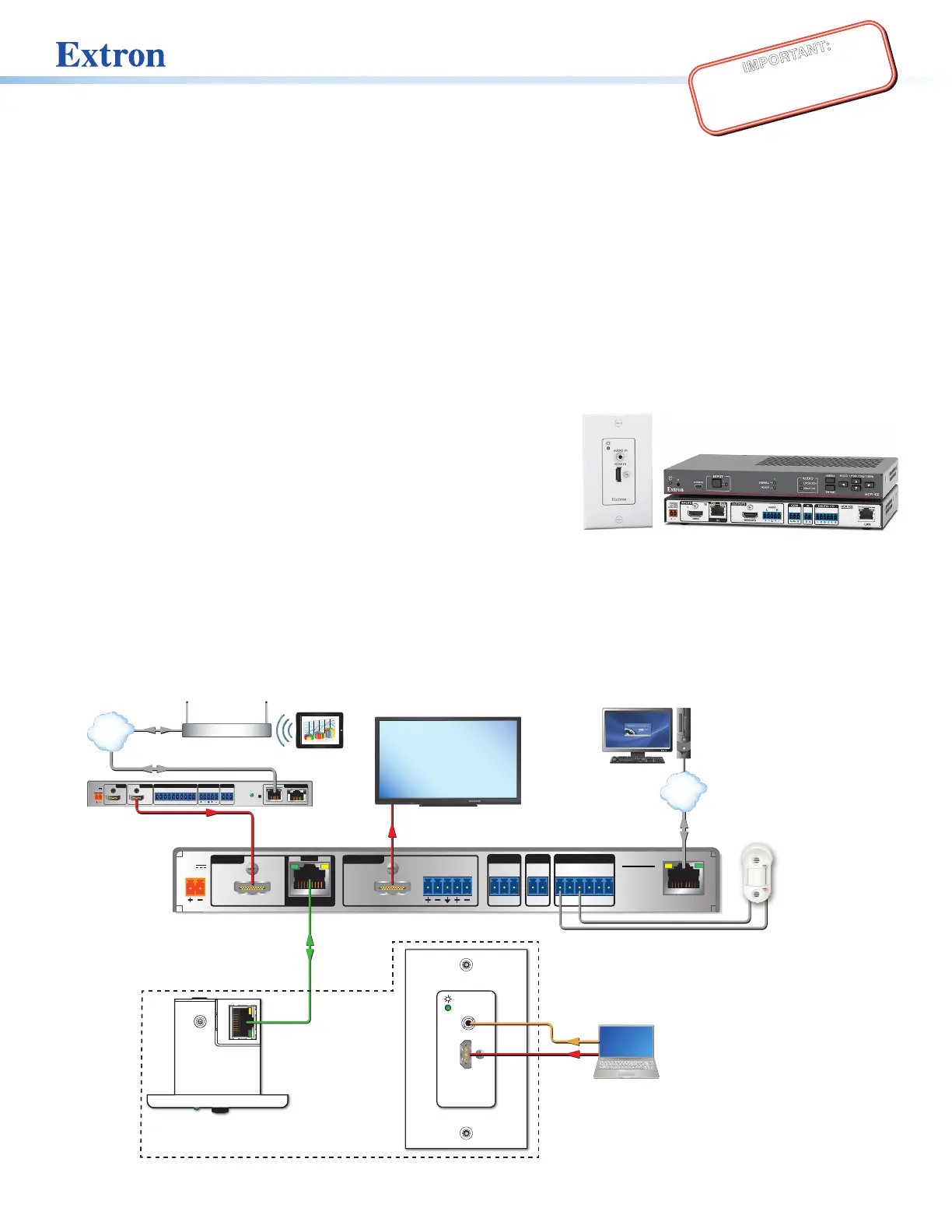
The Extron HC402 system is an AV presentation solution that incorporates a built-in control processor for display control via
HDMI Consumer Electronics Control (CEC), RS-232, IR, or Ethernet. It also includes digital I/O ports.
Each system is a transmitter-receiver pair that is factory-optimized to work together as if it were a single unit.
Together each transmitter-receiver system extends video, audio, and control signals up to 230feet (70m) over a single CATx cable.
Each system offers two auto-input switching modes, one of which (the “last connected” mode) automatically selects sources
based on input signals and also allows manual source selection via buttons. Auto-switching modes can be enabled or disabled
via Extron Product Configuration Software (PCS). The “last connected” auto-switching mode is enabled by default.
The HC402 features two AV inputs and one output. It consists of a one-input transmitter (HCT101D) and a scaling receiver
(HCR102) that has one HDMI input and one connection from the transmitter. The transmitter has a decorator-style wallplate and
can be mounted into a standard US 1-gang junction box. The receiver is wall, furniture, or rack mountable.
HCT101D HCR102
Transmitter
The HCT101D transmitter includes one digital (HDMI) video input and
one analog audio input. It does not include input selection buttons and
LEDs. The extended HDMI video signal can be HDCP-compliant.
Receiver
The HCR102 receiver incorporates a high performance, HDCP compliant
scaler that scales video to provide a consistent output resolution to a
display. It accepts video with resolutions from 480i up to 1920x1200, 1080p, and 2K, and performs upscaling and downscaling
with multiple output rates up to 1920x1200, including HDTV 1080p/60 and 2K. The receiver includes an on-screen display, test
patterns, and EDID Minder.
This setup guide provides instructions for an experienced installer to install the HCT101D and the HCR102. The guide provides
information needed to configure the most essential settings for the system and the receiver. It also describes basic operations using
front panel controls and the on-screen display (OSD) menu system. Full details are available in the HC400 Series User Guide.
POWER
12V
2.0A MAX
INPUTS
OUTPUTS
1
TP
HDMI
LR
AUDIO
HDMI/CEC
SIG
LINK
IN
COMIRDIGITAL I/O
12SGTxRxGG34G
HCR 102
LAN
e
HDMI IN
AUDIO IN
e
HDMI IN
AUDIO IN
Ethernet
PC with
GlobalViewer
Enterprise
TCP/IP
Network
HCR 102
Scaling Receiver
Display
HDMI,
CEC
Twisted Pair
Cable (AV)
230'
HDMI
MODEL 80
FLAT PANEL
HCT 101 D
Transmitter
Top
Front
Extron
OCS 100W
Wall Mount
Occupancy
Sensor
Ethernet
Room
Wireless Access
Point
Tablet
RESET
A/PoEB
POWER
12V
1.7A MAX
HDMIHDMI
TxRxG
RS-232
COM
L
AUDIO
R
OUTPUT
1
CT
2
CT
3
CT
4
CTG+V
CONTACT / TALLY
LAN
INPUT
OUTPUT
Extron
ShareLink Pro 1000
Wireless and Wired
Collaboration
Gateway
HDMI
Ethernet
TCP/IP
Network
Audio
Figure 1. An HC 402 System Application
Product specificaties
| Merk: | Extron |
| Categorie: | Niet gecategoriseerd |
| Model: | HC 402 |
Heb je hulp nodig?
Als je hulp nodig hebt met Extron HC 402 stel dan hieronder een vraag en andere gebruikers zullen je antwoorden
Handleiding Niet gecategoriseerd Extron

26 Maart 2026
4 Maart 2026
11 December 2025
9 December 2025
9 December 2025
9 December 2025
29 November 2025
29 November 2025
23 November 2025
7 November 2025
Handleiding Niet gecategoriseerd
Nieuwste handleidingen voor Niet gecategoriseerd
23 Juli 2026
23 Juli 2026
23 Juli 2026
23 Juli 2026
23 Juli 2026
23 Juli 2026
23 Juli 2026
23 Juli 2026
23 Juli 2026
22 Juli 2026