Ersa 150 S Handleiding


Lees hieronder de đź“– handleiding in het Nederlandse voor Ersa 150 S (11 pagina's) in de categorie Soldeermachine. Deze handleiding was nuttig voor 23 personen en werd door 2 gebruikers gemiddeld met 4.5 sterren beoordeeld

Pagina 1/11
D
1. Betriebsanleitung und beiliegende Sicher-
heitshinweise bitte vollständig durchlesen.
2.
Die Spannungsangabe auf dem Typenschild
muss mit der Spannung der Stromquelle ĂĽber-
einstimmen.
Kleinspannungsausführungen sind Geräte der
Schutzklasse III.
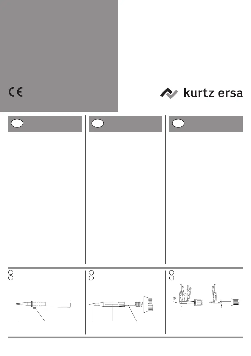
3. Vor dem Aufheizen Sitz der Lötspitze kontrollieren.
a) Außenbeheizte Lötspitzen:
Klemmschraube(n) muss (mĂĽssen)
angezogen sein (siehe Abb. 1a).
b) Innenbeheizte Lötspitzen:
Lötspitze bis Anschlag aufschieben.
Zwischen Lötspitze und Heizkörper darf
kein Luftpolster bestehen.
Die Lötspitze kann durch einfaches Abziehen
bzw. Aufstecken gewechselt werden. Beim
Aufstecken ist der federnde Hebelarm der
Lötspitzenhaltefeder leicht anzuheben, so
dass die Lötspitze ohne Widerstand auf das
Stielrohr aufgeschoben werden kann.
Bitte beachten Sie, dass das Federelement
auf dem Stielrohr auf Anschlag an den
Handgriff herangeschoben ist (s. Abb. 1b).
c)
Nur Ersa Multi-Pro, 15+, 25+, 35+:
(s. Abb.1c)
Vor Inbetriebnahme des
Gerätes ist zu beachten:
1. Read operating instructions and safety
instructions completely.
2. Check that the voltage given on the
nameplate is the same as your source at
the mains.
Tools with low voltages belong to
safety class III.
3. Before heating up make sure that the tip
is properly in position.
a) Tips heated from outside:
clamp screw(s) must be tight (see pic. 1a).
b) Tips heated from inside:
The tip must sit close to the heating
element so that no air is entrapped
between the tip and the heating element.
The tip can be easily exchanged by
taking it off resp. putting on. When
putting it on lift slightly the springy
lever of the fixing clip so that the tip
can be pushed on the shaft of the heater
without resistance.
Please take care that the springy
element on the shaft is pushed up to
the handle (see pic.1b).
c)
Ersa Multi-Pro, 15+, 25+, 35+ only:
(see pic.1c)
1. Lire le mode d’emploi et les instructions
de securité complètement.
2. La tension indiquée sur la plaque
signalétique doit correspondre à celle
du secteur.
Les appareils de basse tension appartien-
nement Ă  la classe de protection III.
3. Avant de chauffer il est recommandé de
contrôler l’ajustement de la panne.
a) Pannes à chauffage extérieur:
la vis de blocage doit être serrée
(v. fig. 1a).
b) Pannes à chauffage intérieur:
La panne doit être bien ajustée sur la ré-
sistance du fer à souder. Il est nécessaire
qu'il n'existe pas de matelas d’air isolant
entre panne et résistance. La panne peut
être échangée simplement par enlever ou
attacher. En attachant le bras de levier
Ă©lastique du ressort de retenue doit ĂŞtre
levé un peu pour que la panne peut être
fixée sur la manche sans résistance.
L’élément élastique sur la manche doit
être poussé jusqu’ à la butée (v. fig.1b).
c) Seulement pour Ersa Multi-Pro,
15+, 25+, 35+: (v. fig.1c)
Außenbeheizte Lötspitzen
Bits heated from outside
Pannes à chauffage exté-
rieur
Lötspitze
Soldering tip
Panne
Klemmschraube
Clamp screw
Vis de blocage
Klemmschlitz
Clamp slit
Fente
Lötspitze
Soldering tip
Panne
Heizkörper
Heating element
RĂ©sistance
Nur Ersa Multi-Pro, 15+, 25+, 35+
Ersa Multi-Pro, 15+, 25+, 35+ only
Seulement pour Ersa Multi-Pro, 25+, 35+
1
b
Innenbeheizte Lötspitzen
Bits heated from inside
Pannes à chauffage intérieur
Spitzenhaltefeder
Fixing clip for bits
Communtateur
Federhaken aus Spitzenbohrung heben (1) und
Spitze mit Flachzange abziehen (2).
Unhook spring hook from the hole (1) and pull
tip off with flat pliers (2).
Mousqueton hors du trou de panne (1) et tirer
cette dernière à l’àide d’une pince plate (2).
c
1
1
a
GB F
Before taking the tool into
use make sure of the fol-
lowing:
Avant la mise en service il
est nécessaire d’observer
les aspects suivants:
*)
*) Wir empfehlen:
Spitzenwechselwerkzeug 3 ZT 00164 *) We recommend:
Tip exchanger 3 ZT 00164 *) Nous recommandons:
Pince de changement de pannes 3 ZT 00164
Betriebsanleitung/Operating instructions/
Mode d’emploi/Instrucciones de servicio/
Istruzioni per l’uso/Instruções de operação/
Handleiding/Kullanma kılavuzu
Lötkolben / Soldering irons /
Fers Ă  souder / Saldatori /
Soldadores / Ferros de soldar/
Soldeerbouten/Havya
Ersa 15+ / 25+ / 35+ / 30 S /
50 S / 80 S / 150 S / 200 /
300 / 550 Multitip1) / Tip 260 /
Minityp S1) / Minor S1) /
Multi-Pro Isotyp 90 S2) / 185 PZS3)
Inbetriebnahme und
Löten
Taking into use for the first
time and soldering
Mise en service et sou-
dage
1. Lötgerät an entsprechendes Stromnetz
anschlieĂźen.
Achtung!
Die Lötspitze darf nur im ausgeschalteten
Zustand und ohne Gewalt entfernt werden.
Neue Lötspitze bis zum Anschlag ein-
schieben.
2. Lötkolben nicht ohne Lötspitze aufheizen.
3. Lötgerät nach der Lötarbeit an der Luft
abkĂĽhlen lassen (nicht mit Wasser
abschrecken).
4. Lötgerät nur auf passenden Ablageständer
ablegen (siehe Abb. 2).
Heizkörper- bzw. Teilewechsel
Das Auswechseln der Heizkörper und
Spitzen darf nur von fachkundigem
Personal durchgefĂĽhrt werden.
Achtung! Nur Originalteile verwenden!
1. Connect soldering tool to suitable
current source.
Attention!
The tip can be removed when the soldering
iron is switched off and without using force.
New tip to be inserted till stopped.
2. Do not heat up soldering iron without tip.
3. After use let the soldering iron cool down
in the air (do not cool off with water).
4. Deposit the soldering iron only on
suitable holder (see pic. 2).
Replacement of the heating ele-
ment
Exchange of heating elements and tips
should only be done by competent persons.
Important! Use only original parts!
1. Relier le fer au secteur adéquat.
Attention!
La panne doit être enlevée sur fer à
souder débranché sans force. La panne
est introduite jusqu’à l’arret.
2. Ne pas chauffer le fer Ă  souder sans
panne.
3. Après le travail de soudure le fer à
souder doit refroidir à l’air (ne pas le
plonger avec l’eau).
4. DĂ©poser le fer Ă  souder seulement dans
un repose-fer convenable (v. fig. 2).
Changement de résistance
Les résistances et pannes peuvent être
changées que par du personnel compétent.
Attention! Utilisez exclusivement les
pièces de rechange originales!
A 18 Nur / only for / seulemnet pour Ersa 30:
Ablegen nur nach Aufstecken der
Sechskant-Auflegescheibe.
Put down only after mounting the
supporting ring.
Deposer seulement après avoir placé
le disque support hexagonal.
Achtung:
Nehmen Sie keine Eingriffe oder Veränderungen
am Lötkolben vor. Reparaturen dürfen nur von
Ersa oder autorisierten Kundendienststellen
vorgenommen werden. Die Geräte beinhalten
strom- und spannungsfĂĽhrende Teile. Bei
unsachgemäßen Eingriffen besteht Lebens-
gefahr.
Nur fĂĽr Isotyp 90 S2)
Das Öffnen dieses Gerätes ist verboten. Re-
paraturen dĂĽrfen nur im Werk durchgefĂĽhrt wer-
den. Bitte an Ersa, Wertheim einsenden.
Nur fĂĽr Minor S/Minityp S/15+/25+/35+
Der Austausch von Heizelementen ist bei die-
sem Gerät nicht möglich.
Warning:
Do not make any repairs or alterations to the
soldering tool. Repairs are only to be carried
out by Ersa or authorized and qualified service
stations.
The equipment incorporates parte under current
and voltage. Inexpert handling can cause death
by shock.
Only for Isotyp 90 S
2)
Do not open the soldering iron!
For safety reasons repairs can only be carried
out by the manufacturer.
Only for Minor S/Minityp S/15+/25+/35+
The change of heating elements is not possible
with this equipment.
Attention:
Vous ne devez en aucun cas intervenir sur le
fer Ă  souder ou y apporter des modifications.
Les réparations doivent être effectuées par Ersa
ou des électricienes qualifiés et autorisés. Les
appareils contiennent des pièces conductrices du
courant ou sous tension. Danger de mort en cas
d’intervention inadéquate.
Seulement pour Isotyp 90S2)
Il est défendu d’ouvrir ce fer à souder. Pour des raisons
de sécurité, ils ne peuvent être réparés qu’en usine.
Seulement pour Minor S/15+/Minityp
S/25+/35+
L'échange des résistances n'est pas possible
pour cet appareil.
FuĂźnoten:
1) Bei der KleinspannungsausfĂĽhrung von
6 V bzw. 12 V bildet das AuĂźenrohr den
RĂĽckleiter fĂĽr die Heizwicklung.
Bitte Potentialverhältnisse beachten.
2) Diese Geräte sind schutzisoliert aufgebaut.
3) Kunststoffschweißgeräte
Footnotes:
1) With the 6 V and 12 V models the shaft of
the iron forms the return conductor for the
heating element. Please pay attention to the
potential differences.
2) Irons are manufactured with safety insulation.
3) Plastic welding tools
Notes:
1) Sur les modèles de 6 et 12 V, le tube extérieur
sert de conducteur de retour Ă  la resistance.
S.v.p., attention à la différence du potentiel.
2) Ces fers à souder sont fabriqués à double
isolation.
3) Fers à souder des matières plastiques.
Ersa 30
Minor S / Minityp S
Ersa-Lötkolben (230 V) werden nach den
Sicherheitsvorschriften der VDE 0700
gefertigt und geprĂĽft.
Ersa soldering irons (230 V) are manufactured
and tested according to the German Engineering
Regulations VDE 0700.
Les fers à souder Ersa (230 V) sont fabriqués et
contrôlés d’après les prescriptions de sécurité
VDE 0700.
A 04
Ersa 50 S / 80 S / 150 S
Isotyp 90 S
2
Ersa Multitip
Tip 260
15+
25+
35+
22
2
185 PZS
A 38 2Ersa 200
300
550
A 17
I E P
Prima della messa in fun-
zione è necessaraio assi-
curarsi di quanto
segue:
A observar antes de la
puesta en servicio:
I saldatori Ersa (230 V) sono fabbricati e control-
lati in base alle norme di sicurezza VDE 0700.
1. Leggere completamente le istruzioni per
l’uso e istruzioni di sicurezza!
2. La tensione indicata sulla targhetta iden-
tificativa deve corrispondere alla tensione
della rete.
Attrezzi con basso voltaggio appartengono
alla classe di sicurezza III.
3. Prima di riscaldare si raccomanda controllare
la posizione della punta.
a) Punte a riscaldamento esterno:
la/le vite/i di arresto deve/devono essere
serrata/e (vedi Fig. 1).
b) Punte a riscaldamento interno:
Spingere le punte fino all’arresto.
Non ci devono essere cuscini d’aria fra
punta e resistenza.
La punta può essere sostituita con semplice
estrazione e inserimento.
Durante l’inserimento il braccio elastico
della leva della molla di sostegno della
punta deve essere un po’ sollevato in
modo che la punta possa venire spinta
sul tubo del manico senza incontrare
resistenza.
Fare attenzione che l’elemento elastico
sia ben spinto fino al manico (Vedi Fig. 1).
c) Ersa Multi-Pro/15+/25+/35+ solo:
(vedi fig. 1c)
Los soldadores Ersa (230 V) están fabricados
y verificados segĂşn las normas de seguridad
VDE 0700.
1. ¡Leer a fondo las instrucciones de
servicio y las instrucciones de seguridad!
2. La tensiĂłn en la placa indicadora debe
corresponder a la tensiĂłn de red.
Las herramientas de bajo voltaje se
engloban dentro de la categorĂ­a III de
seguridad.
3. Antes del calentar, controlar la fijaciĂłn
de la punta de soldar.
a) Puntas con calentamiento desde el
exterior:
Apretar el/los tornillo/s de fijaciĂłn
(véase fig. 1).
b) Puntas con calentamiento inter-
no:
La punta debe dar con el cuerpo.
No debe hallarse ningĂşn colchĂłn de aire
entre la punta de soldar y el elemento de
calefacciĂłn.
Las puntas pueden ser extraidas y
sustiuĂ­das con facilidad.
Para el montaje de la punta hay que levantar
ligeramente el brazo de palanca elástico
del muelle de fijaciĂłn de la punta para
que pueda montar la punta en el vástago sin
resistencia (véase fig. 1).
c) ¡Sólo en el Multi-Pro/15+/25+/35+ de
Ersa! (ver fig. 1c)
Punte a riscaldamento esterno
Punta de calefacciĂłn externa
Pontas de solda com aquecimen-
to exterior
Punte a riscaldamento interno
Punta de calefacciĂłn interna
Pontas de solda com aqueci-
mento
Punta
Punta de soldar
Ponta de solda
Vite di arresto
Tornillo de apriete
Parafuso de aperto
Fessura di
serraggio
Ranura
Punta
Punta de soldar
Ponta de solda
Elemento riscaldante
Resistencia
Elemento térmico
1
b c
11
a
Ersa Multi-Pro/25+/35+ solo
Solamente para el
Multi-Pro/15+/25+/35+ de Ersa
Apenas Ersa Multi-Pro/25+/35+
Molla di sostegno punta
Muelle de fijaciĂłn de la punta
Ranhura de aperto
Sganciare la molla dal foro (1).
Estrarre la punta con pinze piatte (2).
Soltar el gancho elástico de la ranura (1) y
estirar de la punta con unas tenazas de boca
plana (2).
Levantar o gancho da mola de furação (1) e reti-
rar a ponta com um alicate de bico fino (2).
*) Raccomandiamo:
Pinza di sostituzione pinze 3 ZT 00164 *) Recomendamos:
Tenacilla 3 ZT 00164 *) Recomendamos: Ferramenta de troca de
pontas 3 ZT 00164
Os ferros de soldar da Ersa (230 V) sĂŁo fabri-
cados e testados segundo as instruções de
segurança da VDE 0700.
1. Ler completamente as instruções de opera-
ção e as recomendações de segurança!
2. A tensão indicada na placa de identificação
deve corresponder Ă  tensĂŁo da fonte de
corrente. As ferramentas de baixa tensĂŁo
pertencem à classe de proteção III.
3. Antes de aquecer certifique-se de que a
ponta de solda está posicionada correta-
mente.
a) Pontas de solda com aquecimen-
to exterior:
O(s) parafuso(s) de aperto deve(m) estar
apertado(s) (ver figura 1a).
b)
Pontas de solda com aquecimento
interior:
Conduzir a ponta de solda até se ajustar ao
encosto. Entre a ponta de solda e o elemen-
to térmico não pode haver ar.
A ponta de solda pode ser substituĂ­da por
meio de simples retirada e colocação. Ao
colocá-la, o braço de alavanca atuado a
mola da mola retentora deve ser ligeiramente
levantado de modo que a ponta de solda
possa ser fixada no tubo sem resistĂŞncia.
Observar que o elemento de mola no tubo
tenha sido conduzido até o encosto do
cabo.
c) Apenas Ersa Multi-Pro/15+/25+/35+:
(ver figura 1c)
Antes da colocação em
funcionamento do apa-
relho deve-se observar:


Product specificaties

Merk: Ersa
Categorie: Soldeermachine
Model: 150 S

Heb je hulp nodig?

Als je hulp nodig hebt met Ersa 150 S stel dan hieronder een vraag en andere gebruikers zullen je antwoorden


Handleiding Soldeermachine Ersa

Handleiding Soldeermachine

Nieuwste handleidingen voor Soldeermachine