Erica Synths Bassline Handleiding
Erica Synths Niet gecategoriseerd Bassline
Bekijk gratis de handleiding van Erica Synths Bassline (6 pagina’s), behorend tot de categorie Niet gecategoriseerd. Deze gids werd als nuttig beoordeeld door 19 mensen en kreeg gemiddeld 4.1 sterren uit 6 reviews. Heb je een vraag over Erica Synths Bassline of wil je andere gebruikers van dit product iets vragen? Stel een vraag
Pagina 1/6
GUIDE TO ASSEMBLY OF ERICA SYNTHS BASSLINE MODULE
If you are reading this, most probably, you are
about to build Erica Synths DIY BASSLINE module.
The module is 45mm deep, skiff friendly, has solid
mechanical construction and doesn’t require wiring.
Erica Synths Bassline is full analogue synth
voice module for ultimate acid basslines. It features
highly stable AS3340-based VCO with three
waveforms, a filter inspired by Erica Synths Acidbox
and unique feature –transistor-based suboscillator.
Accent provides more expression to the bassline, by
adding volume and opening the VCF slightly.
The Bassline kit comes in three versions:
1)Set of 2 PCBs + rare ICs + mechanical parts (PCB
connectors and spacer),
2)Set of 2 PCBs + rare ICs + mechanical parts (PCB
connectors and spacer)+ panel,
3) Full kit.
FEATURES:
•Full analogue circuit
•Great 1V/oct tracking
•Simultaneous Triangle, Square and Master
outputs
•Accent
•Transistor-based suboscillator
•VCF and VCA decay envelopes
•LP/BP VCF
•External VCO FM and VCF cutoff CV inputs
SPECIFICATIONS:
•Pitch rangeC0-C8
•Audio output amplitude10Vptp
•CV amplitude (full span)-5V -+5V
•Panel width16HP
•Module depth45mm
•Power consumption80mA @+12V,
40mA@-12V
1
3
4
2
56
7
8
9
1
2
3
4
5
6
7
8
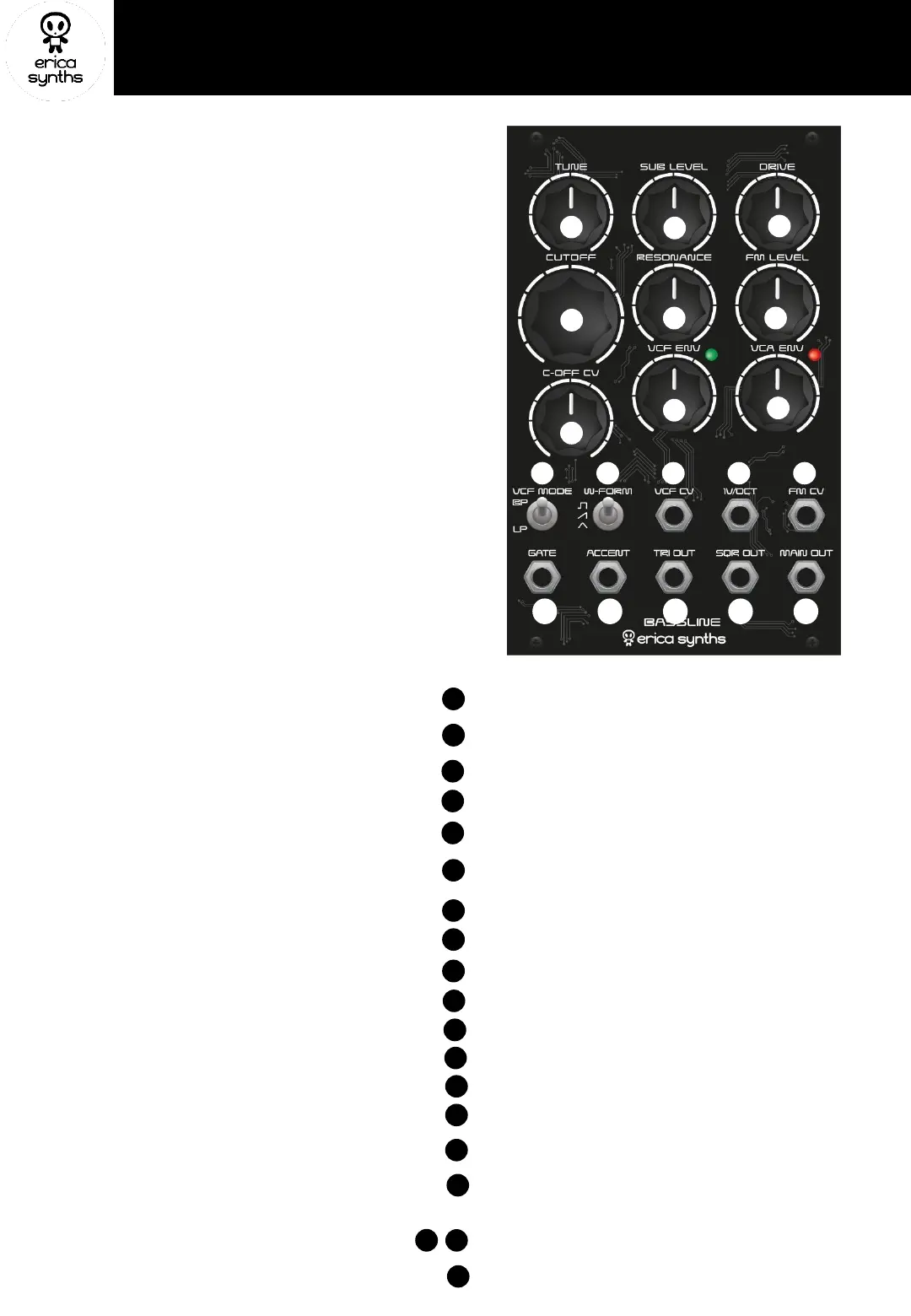
Set the initial tune of the VCO
Add some power to the sound! This is octave down transistor-based
suboscillaotrlevel control and effects Main output only
Set desired overdrive level! It effects Main output only
This is an external FM level attenuator. You can also do some self-
modulation by patching TRI OUT in to FM IN and increasing FM level.
Adjust VCF cutoff CV level! If nothing is patched in C OFF CV input, it
adjusts VCF envelope impact on the cutoff
Adjust the VCF cutoff envelope decay time
9
Adjust the VCA envelope decay time. Full CW setting will open
the VCA even the gate is not present
1011121314
1516171819
10
Select the VCF mode
11
Select the VCO waveform that is sent to the master output
12
This is an external CV input to control the VCF cutoff
13
This is the VCO 1V/oct input. It tracks well over 9 octaves
14
This is the VCO FM input
15
16
This is the Accent input. +10V CV will increase the volume and
open the VCF slightly to an expression to the bassline
17
18
19
This is the main output of the module
Big knobs are for VCF cutoff manual control!
Adjust the VCF resonance! The filter is the same as on DIY Polivoks
VCF, and it’s capable of extreme resonance sweeps.
This is the Gate input. It accepts gate from any sequencer and
sends it to the VCF and VCA envelopes simultaneously
These are additional VCO outputs, and they are not affected by VCF
and VCA. You can use them as additional sound sources that are in
tune with your bassline
Product specificaties
| Merk: | Erica Synths |
| Categorie: | Niet gecategoriseerd |
| Model: | Bassline |
Heb je hulp nodig?
Als je hulp nodig hebt met Erica Synths Bassline stel dan hieronder een vraag en andere gebruikers zullen je antwoorden
Handleiding Niet gecategoriseerd Erica Synths

6 April 2026
3 April 2026
2 April 2026
1 April 2026
1 April 2026
31 Maart 2026
31 Maart 2026
31 Maart 2026
31 Maart 2026
Handleiding Niet gecategoriseerd
Nieuwste handleidingen voor Niet gecategoriseerd
7 Juli 2026
7 Juli 2026
7 Juli 2026
7 Juli 2026
7 Juli 2026
7 Juli 2026
7 Juli 2026
7 Juli 2026
7 Juli 2026
7 Juli 2026