Eoslift E20MP Handleiding
Eoslift
Niet gecategoriseerd
E20MP
Bekijk gratis de handleiding van Eoslift E20MP (15 pagina’s), behorend tot de categorie Niet gecategoriseerd. Deze gids werd als nuttig beoordeeld door 102 mensen en kreeg gemiddeld 3.8 sterren uit 51.5 reviews. Heb je een vraag over Eoslift E20MP of wil je andere gebruikers van dit product iets vragen? Stel een vraag
Pagina 1/15

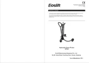
Thank you for using our scale pallet trucks. The scale pallet truck, equipped with a high-precision weighing
system METTLER TOLEDO, is made of high quality steel and is designed for the horizontal lifting and
transporting loads on a pallet or standardized containers on a level, fixed base. For your safety and correct
operation, please carefully read this instruction before using it.
NOTE: All of the information reported herein is based on data available at the moment of printing. We
reserve the right to modify our own products at any moment without notice and incurring in any sanction. So,
it is suggested to always verify possible updates.
BEFORE YOU BEGIN
Scale Pallet Truck
Operating Instructions
E20M/E20MP
E20M/E20MP
E20M/E20MP
Eoslift Warehousing Equipment Co., Ltd.
No.99, Yanjia Road, Yuantong Town, Haiyan, Zhejiang
No.99, Yanjia Road, Yuantong Town, Haiyan, Zhejiang
No.99, Yanjia Road, Yuantong Town, Haiyan, Zhejiang
No.99, Yanjia Road, Yuantong Town, Haiyan, Zhejiang
Eoslift Warehousing Equipment Co., Ltd.

2.Mounting Indicator
2.1 Screw out three hex. screws (201-4) on the indicator (201) .
2.2 Fix the protecting cover (201-2) on the frame with hex. screw (210).
2.3 Connect the plug of load cell and socket of the indicator.
2.4 Tighten three hex. screws (201-4).
1.Technical Specifications
1
RATED CAPACITY 2,000kg/4,500lbs
WORKING ENVIRONMENT Dry
MIN. /MAX. FORK HEIGHT 85/200mm
WEIGHT ACCURACY +/- 0.5‰ of applied load
WIDTH ACROSS FORKS 560mm/705mm
FORK LENGTH 1150mm/1220mm
1 2
CONTENTS
Page 1
Page 1
Page 2
Page 2
Page 2
Page 3
Page 5
Page 6
Page 7
Page 8
Page 9
Page 15
1 Technical Specifications
2 Mounting Indicator
3 To Attach Draw-Bar to Pump Unit
4 To Adjust Release Device
5 Maintenance
6 Safety Guidance
7 Trouble shooting
8 Overview
9 Charging the Battery
10 Operation
11 Setup
12 Terminal Maintenance
3
4 5 6
Fig. 1

5.3. DAILY CHECK AND MAINTENANCE
Daily check of the pallet truck can limit the abrasion as much as possible. Special attention should be paid
to the wheels, the axles, as thread, rags, etc. It may block the wheels. The forks should be unloaded and
lowered to the lowest position when the job is finished.
5.4. LUBRICATION
All bearings and shafts are provided with long-life grease at the factory. The only thing you need to
provide to the lubrication points is long-life grease at monthly intervals or after each time the truck is
cleaned thoroughly.
5.5 Replace the battery
A) Remove the cover board (201-05)
B) Put in 4 batteries
C) Put the cover board back
2
3
3.To Attach Draw-bar To Pump Unit
When attaching the handle, you had better squat just behind the pallet truck. Then you:
3.1 Insert the draw-bar onto the pump piston, and then use a hammer to insert the axle with hole (105) into
the hydraulic pump and draw-bar from the right to left. (See fig. 2 ).
3.2 Adjust the control handle(117) to the ‘LOWER’ position, then pass the adjusting nut(104), adjusting
bolt(103) and chain(102) through the hole of axle(105) with your hand (See fig. 3).
3.3 Press the draw-bar (110), down, take away the pin(348) (See Fig. 1).
3.4 Let the control handle (117) on ‘RAISE’ position, then raise the lever plate (315) with the pin and
insert the adjusting bolt(103) into the front slot of lever plate (315), note to keep the adjusting nut (104)
on the bottom side of the lever plate.
3.5 Use a hammer to tap another elastic pin (106) into the axle with hole (105).
The draw-bar is now assembled to the pump.
Fig. 2 Fig. 3
4.To Adjust Release Device
On the draw-bar of this pallet truck, you can find the control handle(117) which can be regulated in three
positions :
Raise -handle down
Drive -handle in center position
Lower -handle upthe lever moves back to the drive position when released.
However if they have been changed, you can adjust them according to the following steps:
4.1 If the forks elevate while pumping in the DRIVE position, turn the adjusting nut (104) on the adjusting bolt
(103) or screw (318) clockwise until pumping action does not raise the forks and the DRIVE position
works properly.
4.2 If the forks descend while pumping in the DRIVE position, turn the nut(104) or screw(318) counter-
clockwise until the forks stop descending.
4.3 If the forks do not descend when the control handle (117 ) is in the LOWER position, turn the nut (104) or
screw (318) clockwise until raising the control handle (117) lowers the forks. Then check the DRIVE
position according to item 3.1 and 3.2 to be sure the nut (104) and screw(318) is in the proper position.
6.Safety Guidance
6.1 Operator should read all warning signs and instructions both here and on the pallet truck before using
this truck.
6.2 Do not use on a slope.
6.3 Do not operate a pallet truck unless you are familiar with them and have been trained or authorized to do
so.
6.4 Do not operate a pallet truck unless you have checked its condition. Give special attention to the wheels
or rollers, the draw-bar unit, the fork unit, the lever plate, etc. .
6.5 To pull the truck, always move the control handle into the drive position. This makes the draw-bar easier
to move and depressurizes the pump section of the hydraulics. This preserves the hydraulic seals and
the valve components. A long service life can be expected.
6.6 Do not take up any people on the pallet truck.
6.7 The operator had better take on gloves for labor protecting.
6.8 When the goods have been transported, all people should be away from the forks for 600mm.
6.9 Do not load goods like fig. 5/B .
6.10 Do not load goods over maximum capacity.
6.11 At other special condition or place, the pallet truck should be carefully operated.
The pallet truck is largely maintenance-free.
5.1. OIL
Please check the oil level every six months. The oil can be hydraulic oil: ISO VG32, its viscosity should be
30℃St at 400℃, total volume is about 0.4lt.
5.2. BANISHING THE AIR
The air may come into the hydraulic oil because of transportation or pumping in the upset position. This
will lead to the problem that the forks can’t be elevated while pumping in the RAISE position. The air can
been removed in the following way: Adjust the control handle (117) on the LOWER position, then move the
draw-bar up and down for several times.
5.Maintenance
105
103
315
104
348
347
346
110
102
109
108
Product specificaties
| Merk: | Eoslift |
| Categorie: | Niet gecategoriseerd |
| Model: | E20MP |
Heb je hulp nodig?
Als je hulp nodig hebt met Eoslift E20MP stel dan hieronder een vraag en andere gebruikers zullen je antwoorden
Handleiding Niet gecategoriseerd Eoslift
25 Augustus 2025

14 Juli 2023

14 Juli 2023

14 Juli 2023

14 Juli 2023

14 Juli 2023

14 Juli 2023

14 Juli 2023

14 Juli 2023

14 Juli 2023
Handleiding Niet gecategoriseerd
- Ansel
- CDA
- Kitronik
- Lightspeed
- Cooper Lighting
- Foppapedretti
- Doughty
- Boss
- Corona
- Sonnet
- Konyks
- Juki
- Craftsman
- Indiana Line
- Schaudt
Nieuwste handleidingen voor Niet gecategoriseerd

15 September 2025

15 September 2025

EK Water Blocks EK-Quantum Velocity³ 1700/1851/AM5 Handleiding
15 September 2025
15 September 2025

15 September 2025
15 September 2025

15 September 2025

15 September 2025

15 September 2025

15 September 2025