Enermax ETS-F40-FS ARGB Handleiding
Enermax
Hardwarekoeling
ETS-F40-FS ARGB
Bekijk gratis de handleiding van Enermax ETS-F40-FS ARGB (4 pagina’s), behorend tot de categorie Hardwarekoeling. Deze gids werd als nuttig beoordeeld door 54 mensen en kreeg gemiddeld 4.1 sterren uit 27.5 reviews. Heb je een vraag over Enermax ETS-F40-FS ARGB of wil je andere gebruikers van dit product iets vragen? Stel een vraag
Pagina 1/4

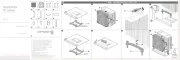
Required moun�ng parts:
AETS-F40-FS cooler X 1 CBack Plate X 1
D E F
GIntel Mounting Plate
X 2
Intel Mounting Plate X 2
HAMD Mounting Plate X 1 Nut X 4
Nut X 4
I
Washer X 4
Back Plate X 1 Washer X 4
Position Screw X 4
Position Screw X 4
Stand-off X 4
Stand-off X 4
J K AMD Mounting
Screw X 4
LThermal Grease
X 1
Intel LGA
2011/2066
Screw X 4
MFan Clip X 4
BFan X 1
©2020 ENERMAX TECHNOLOGY CORPORATION. All right reserved. Specifications are subject to
change without prior notice. Some trademarks may be claimed as the property of others.
U s e r ’ s M a n u a l
ETS-F40-FS - Part List Chapter 1 * Intel (LGA1366/1200/115X/775) Installa�on
Step 1.1 Step 1.2 Step 1.3
Chapter 2 * Intel (LGA201x/2066) Installa�on
Jul. 2020
Notice: Actual specifications/ product parts may vary according to different regions or countries.
Required moun�ng parts:
Intel Mounting Plate X 2 Nut X 4Intel LGA 2011/2066 Screw X 4
I
G
* ensure the position screw aligning to the back plate
* please ensure a proper connection to the motherboard.
C
D
E
LGA1200/115X
EN
DE
FR
IT
PL
ES
RU
TW
CN
KR
JP
IN
Pre-installation, before attaching the back plate on the rear side of motherboard.
《 If your CPU platform is Intel LGA2011/2011-3/2066, please skip to step 2.1》
Vor der Installation, bevor die Backplate auf der Rückseite der Hauptplatine angebracht wird.
《Wenn Sie einen LGA2011/2011-3/2066-Sockel verwenden, gehen Sie bitte zu Schritt 2.1 über》
Assemblage du cadre de montage du ventirad
Positionnez les 4 vis (E), et fixez-les soigneusement à la plaque arrière (C) à l’aide des rondelles (D)
《S’il s’agit d’un processeur Intel LGA2011/2011-3/2066, passez à l'étape 2.1》
Preinstallazione, prima di fissare la piastra posteriore sul retro della scheda madre.
《Se la piattaforma CPU è Intel LGA2011/2011-3/2066, si prega di passare al punto 2.1》
Sebelum Instalasi, sebelum memasang back plate di sisi belakang motherboard
Jika Platform CPU Anda Intel LGA LGA2011/2011-3/2066, lanjutkan ke langkah 2.1
Instalacja wstępna, przed podłączeniem płyty tylnej z drugiej strony płyty głównej
《Platformy Intel LGA2011/2011-3/2066: Proszę przejść do punktu 2.1》
Pre-instalación, antes de fijar la placa posterior en el lado posterior de la placa base.
《Si su plataforma de CPU es Intel LGA2011/2011-3/2066, por favor vaya directamente al paso 2.1》
Установите винты для крепежной пластины в соответствующие отверстия для вашего процессора.
Закрепите винты шайбами.
《Если ваша CPU платформа является Intel LGA2011/2011-3/2066, пожалуйста, перейдите к шагу номер 2.1》
在背板上依系統CPU腳位所標示的孔位插入定位螺絲並套上墊圈 固定。
《如果您的主機板是Intel LGA2011 / 2066,請直接跳至步驟2.1。》
在背板上依系统CPU脚位所标示的孔位插入定位螺丝并套上垫圈 固定。
《如果您的主板是Intel LGA2011 / 2066,请直接跳至步骤2.1。》
백플레이트(C) 구멍에 맞추어 포지션 스크류(E)를 삽입 후 와셔(D)로 고정하세요.
CPU 플랫폼이 Intel LGA2011/2011-3/2066 인경우, Step 2.1 로 가세요》
マザーボード背面にバックプレートを取り付ける際の事前準備:ポジションスクリューをバックプレートの
適切なネジ穴に挿入し、ワッシャーを使用してポジションスクリューを固定してください。
Intel LGA2011/2011-3/2066をお使いの方はステップ2.1に進んでく ださい
EN
DE
FR
IT
PL
RU
TW
CN
KR
JP
Attaching the back plate on rear of motherboard
Anbringen der Backplate auf der Rückseite der Hauptplatine.
Fixez la plaque arrière au dos de votre carte-mère à l’aide des entretoises (F)
Fissaggio della piastra posteriore sul retro della scheda madre.
Przymocowanie płyty tylnej z drugiej strony płyty głównej
ES Fijar la placa posterior en la parte posterior de la placa base.
IN Pasang back plate di bagian belakang motherboard
Установите крепежную пластину на обратной стороне материнской платы.
Установите промежуточные стойки на винты.
將套有螺絲定位套及定位螺絲的背板,裝於主機板背面,再從主機板正面將定位膠環放入定位
螺絲內。
将套有螺丝垫圈 定位螺丝的背板,装于主板背面,再从主板正面将定位胶环放入定位螺丝内。
메인보드 뒷면에 백플레이트를 설치 하신 후 스탠드 오프(F)지지대를 넣어 주세요.
Step1.1で組んだバックプレートをマザーボード背面に取り付け、
表面に出たポジションスクリューにスタンドオフを装着してください。
EN
DE
FR
IT
PL
RU
TW
CN
KR
JP
Install the Intel mounting plates and fasten the nuts to fix back plate.
Installieren Sie die Intel-Halterungen und befestigen Sie die Muttern, um die Backplate zu fixieren.
Installez les supports de fixation Intel (G) et fixez-les à l’aide des écrous (I) à la plaque arrière
Installare le piastre di montaggio Intel e inserire i dadi per fissare la piastra posteriore
Zainstaluj płyty montażowe Intel i dokręć nakrętki w celu zamocowania płyty tylnej
ES Instale las placas de ensamblaje Intel y apriete las tuercas para fijar la placa posterior.
IN Pasang plat mounting intel dan kencangkan mur untuk memperbaiki back plate.
Установите крепежные пластины Intel на винты и закрепите их гайками.
將支架安裝於定位螺絲上並鎖上螺帽。
将支架安装在定位螺丝上,并锁上螺帽。
인텔 마운팅 플레이트(G)를 설치하여 너트(I)로 단단히 고정하세요.
スタンドオフの上にIntel用マウンティングプレートを設置した後、ナットを使い固定してください。
1
AETS-F40-ARGB cooler
X 1
CBack Plate X 1
D E F
GIntel Mounting Plate
X 2
HAMD Mounting Plate X 1 Nut X 4
I
Washer X 4 Position Screw X 4 Stand-off X 4
J K AMD Mounting
Screw X 4
LThermal Grease
X 1
Intel LGA
2011/2066
Screw X 4
MFan Clip X 4
BARGB Fan X 1
ETS-F40-BK(W)-ARGB - Part List
Notice: Actual specifications/ product parts may vary according to different regions or countries.
2
AETS-F40-BK cooler X 1 CBack Plate X 1
D E F
GIntel Mounting Plate
X 2
HAMD Mounting Plate X 1 Nut X 4
I
Washer X 4 Position Screw X 4 Stand-off X 4
J K AMD Mounting
Screw X 4
LThermal Grease
X 1
Intel LGA
2011/2066
Screw X 4
MFan Clip X 4
BFan X 1
ETS-F40-BK - Part List
Notice: Actual specifications/ product parts may vary according to different regions or countries.
3 4
6 7 85
INTEL
F
INTEL
ETS-F40-BK ETS-F40-BK-ARGB
ETS-F40-W-ARGB
ETS-F40-FS


AMD stock back plate
(included with the motherboard)
AMD Mounting Screw X 4
AMD Mounting Plate X 1 Stand-off X 4
:
J
I
G
J
F
K
B
EN
DE
FR
IT
PL
RU
TW
CN
KR
JP
Fasten the Intel LGA 2011 / 2066 screws to the motherboard. Install the mounting plates on the
position screws and fasten the nuts.
Schrauben Sie die Intel LGA 2011 / 2066-Montageschrauben in die passenden Gewinde des
Motherboards. Stecken Sie die Intel-Montagehalterung auf die Montageschrauben und verschrauben
Sie diese mit den Muttern.
Positionnez les écrous entretoises Intel (J), installez les supports de fixation Intel (G) et fixez-les
enfin à l’aide des écrous (I)
Fissare le viti di montaggio Intel LGA 2011 / 2066 alla scheda madre. Installare le piastre di
montaggio Intel sulle viti di posizione e serrare i dadi
Wkręć śruby montażowe (platformy Intel LGA2011 / 2066) w odpowiednie otwory na płycie głównej.
Zainstaluj płyty montażowe na śrubach pozycjonujących i dokręć nakrętki.
ES Apriete las tuercas del Intel LGA 2011/2066 en la placa base. Instale las placas de
ensamblaje en los tornillos de posición y apriete las tuercas.
IN Kencangkan sekrup Intel LGA 2011/2066 ke motherboard. Pasang plat mounting pada sekrup
posisi dan kencangkan mur.
Затяните винты «Intel LGA 2011 / 2011-3 / 2066» на материнской плате. Установите крепёжные
пластины на винты и закрепите их гайками.
將LGA 2011 / 2066螺絲固定於主板上。將支架安裝於定位螺絲上並鎖上螺帽。
将LGA 2011 / 2066螺丝固定在主板上,将支架安装在定位螺丝上,并锁上螺帽。
마더보드에 INTEL 2011/2066 나사(J)로 고정해 주세요. 인텔마운팅플레이트(G)를 설치 하시고
너트(I)로 단단히 고정하세요.
Intel LGA201x/2066用のポジションスクリューを4箇所に取り付けた後、Intel用マウンティングプレートを
設置し、ナットを使い固定してください。
EN
DE
FR
IT
PL
RU
TW
CN
KR
JP
Put the stand-off onto the screw threads of the backplate.
Setzen Sie die Abstandhalter auf die Schraubengewinde der Backplate.
Positionnez les entretoises (F) sur le filetage des vis de la backplate
Posizionare i distanziatori in plastica sui filetti delle viti della piastra posteriore
Umieść plastikowe tuleje dystansowe na gwintach na śruby w płycie tylnej
ES Coloque el espaciador en la rosca del tornillo de la placa posterior.
IN Letakkan stand-off ke ulir sekrup back plate
Установите промежуточные стойки на отверстия для крепления.
將定位膠環放在AMD 背板螺紋上。
将定位胶环放在AMD 背板螺纹上。
4개의 스탠드오프(F)를 올려 놓으세요.
バックプレートのネジ穴に合わせてスタンドオフを設置してください。
EN
DE
FR
IT
PL
RU
TW
CN
KR
JP
Fix the AMD mounting plate using the four AMD mounting screws.
Befestigen Sie die AMD-Halterung mit den vier AMD-Schrauben.
Fixez la plaque de montage AMD à l’aide des 4 vis de montage (K) fournies
Fissare la piastra di montaggio AMD utilizzando le quattro viti di montaggio
Zamocuj płytę montażową AMD czterema śrubami montażowymi
ES Fije la place de ensamblaje AMD mediante los cuatro tornillos de ensamblaje del AMD.
IN Perbaiki plat mounting AMD menggunakan empat sekrup mounting AMD.
Установите крепежную пластину AMD и закрепите винтами.
將 AMD 螺絲安裝在 AMD 支架上固定。
将 AMD 螺丝安装在 AMD 支架上固定。
4개의 AMD 마운팅 스크류(K)를 이용하여 AMD 마운팅 플레이트를 고정하세요.
スタンドオフの上にAMD用マウンティングプレートを設置した後、AMD用マウンティングスクリューを使い
固定してください。
EN
DE
FR
IT
PL
RU
TW
CN
KR
JP
Carefully tighten the screws until you feel a slight resistance
Ziehen Sie die Schrauben vorsichtig an, bis Sie einen leichten Widerstand spüren.
Positionnez le point de fixation du ventirad au dessus du processeur, et serrez soigneusement
les vis jusqu’à ce que vous rencontriez une légère résistance
Stringere attentamente le viti finché non si avverte una leggera resistenza
Ostrożnie dokręcaj śruby, aż do wyczucia lekkiego oporu
ES Apriete los tornillos con cuidado hasta que note un poco de resistencia.
IN Kencangkan sekrup dengan hari-hati sampai anda merasa tidak bisa memutarnya.
Установите кулер на процессоре, затем закрепите винты.
將散熱器置於CPU上並鎖上底座彈簧螺絲。
将散热器放置于CPU上,并锁紧底座弹簧螺丝。
CPU에 히트싱크를 올려 놓으신 후 드라이버를 이용하여 나사를 단단히 조여 주세요.
CPUの上に本体を設置し、少しテンションがかかるまでネジを締めてマウンティングプレートに固定
してください。注意:本体の向きに注意してください
EN
DE
FR
IT
PL
RU
TW
CN
KR
JP
Attaching the fan to the cooler and connecting the 4 pin header to the CPU fan power socket.
Befestigung des Lüfters am Kühler und Anschluss des 4-Pin-Steckers an der
CPU-Lüfter-Strombuchse.
* Fixez le ventilateur (B) au radiateur (A) à l’aide des clips (M), puis raccordez le connecteur
4 broches à la prise CPU Fan de votre carte-mère
Collegamento della ventola al dissipatore di calore e collegamento del connettore a 4 pin alla presa
di alimentazione della ventola della CPU
Mocowanie wentylatora do coolera i podłączenie 4 pinowego złącza główkowego do gniazda
zasilania wentylatora procesora
ES Fijar el ventilador al refrigerador y conectar el encabezado de 4 clavijas al zócalo de alimentación
del ventilador de la CPU.
IN
EN
DE
FR
IT
PL
RU
TW
CN
KR
JP
ES
IN
EN
DE
FR
IT
PL
RU
TW
CN
KR
JP
ES
IN
Pasang fan ke cooler dan hubungkan header 4 pin ke soket daya fan CPU.
Установите венилятор и подключите 4 пин разъем PWM к материнской плате. Обратите при
этом внимание на направление воздушного потока.
將風扇固定回散熱器上。將PWM風扇 4pin電源接頭與主機板連接。
将风扇固定回散热器上。将PWM风扇 4pin电源接头与主板连接。
쿨러를 부착 한 후 4핀 커넥터를 메인보드 CPU FAN
헤더에 연결해 주세요.
ファンクリップを使用し、ファンを本体に固定してください。冷却ファンの4ピンコネクタをマザーボードの
CPUファン給電ソケットに接続してください。注意:冷却ファンの向きに注意してください
Connect the top cover 3pin ARGB connector to the fan ARGB hub as illustrated way. Then,
connect the sync cable to a supported motherboard with 3pin (5VDG) ARGB header. Connect the sync cable to a supported motherboard with ARGB header.
Schließen Sie den 3-Pin-ARGB-Anschluss der Oberblende wie abgebildet an den ARGB-Anschluss
des Lüfters an. Schließen Sie dann das Synchronisierungskabel an eine unterstützte Motherboards
mit 3pin (5VDG)-ARGB-Stecker an.
Verbinden Sie das Sync-Kabel mit einem kompatiblen Motherboard mit ARGB-Header.
Branchez le connecteur ARGB à 3 broches au hub ARGB du ventilateur comme illustré. Ensuite,
connectez le câble de synchronisation ARGB à l’emplacement prévu sur une carte mère dotée d’un
connecteur ARGB à 3 broches (+5V/D/-/G).
Si la carte mère prend en charge le connecteur RGB (ADD headers): connectez le câble de
synchronisation ARGB à la carte mère.
Collegare il connettore ARGB a 3 pin del coperchio superiore all'hub ARGB della ventola come
illustrato. Quindi, collegare il cavo di sincronizzazione a una scheda madre supportata con
connettore ARGB a 3 pin (5VDG).
Se la scheda madre è fornita di connettori ARGB compatibili, collegare il cavo ARGB Sync alla
scheda madre.
Hubungkan kabel Sync ke motherboard yang support dengan header ARGB.
Podłącz 3-pinowe złącze ARGB pokrywy górnej do huba ARGB wentylatora, zgodnie z ilustracją.
Następnie, podłącz kabel synchronizacji do obsługiwanej płyty głównej, z 3-pinowym złączem
główkowym (5VDG) ARGB.
Jeśli płyta główna OBSŁUGUJE adresowalne nagłówki RGB (ADD): podłącz kabel synchronizacyjny
ARGB do płyty głównej.
Conecte el conector ARGB de 3 clavijas de la tapa superior al concentrador ARGB del ventilador
como se muestra en la ilustración. A continuación, conecte el cable de sincronización a una placa
base admitida mediante el encabezado ARGB (5VDG) de 3 clavijas.
Conecte el cable de sincronización a una placa base admitida con un encabezado ARGB.
Hubungkan konektor top cover ARGB ke hub fan ARGB seperti ilustrasi.Kemudian, hubungkan
kabel Sync ke motherboard yang support dengan header 3 pin (5VDG) ARGB header.
Подключите 3-контактный разъем ARGB верхней крышки к концентратору ARGB вентилятора,
как показано на рисунке. Затем подключите кабель синхронизации к поддерживаемой
материнской плате с 3-контактным (5VDG) разъемом ARGB.
Если материнская плата поддерживает функцию ARGB, подключите кабель синхронизации
ARGB к материнской плате.
將頂蓋的3pin ARGB接頭與風扇的插座連接(如上圖所示)。接著,再將RGB同步線連接到主機板的
3pin ARGB (5VDG) 接口。
若您的主機板有支援addressable RGB (ADD headers)功能:將RGB同步線連接到主機板的 ARGB
4Pin接口。
将顶盖的3pin ARGB接头与风扇的插座连接(如上图所示)。接着,再将RGB同步线连接到主板的
3pin ARGB (5VDG) 接口。 若您的主板有支援addressable RGB (ADD headers)功能:将RGB同步线连接到主板的ARGB 4Pin接口。
그림과 같이 3핀 ARGB 커넥터를 팬 ARGB 허브에 연결을 한 후 동기화 케이블을 메인보드
3핀(5VDG), 5V ARGB 헤더에 연결을 해주세요. 마더보드가 RGB (ADD 헤더를) 지원하는 경우: 동조 케이블을 마더보드에 연결하십시오.ARGB
図のように、トップカバーのARGBコネクター(3ピン)をファンのARGBハブに接続します。
次に、同期ケーブルをマザーボードのARGBヘッダー(5VDG)に接続します。
マザーボードがアドレッサブル型ARGBに対応している場合、 ARGB SYNC用ケーブルをマザーボードに接続
してください。
DE
FR
IT
PL
RU
TW
CN
KR
JP
Tragen Sie eine dünne Schicht Wärmeleitpaste auf die Oberfläche der CPU auf. Entfernen
Sie die Sicherheitsfolie von der Bodenplatte des CPU-Kühlers.
Appliquez une petite goutte de pâte thermique au centre de la surface du processeur
Applicare omogeneamente la pasta termica sulla superficie della CPU con la spatola.
Rimuovere la pellicola protettiva dalla base del disspatore.
Nanieś równo szpachelką pastę termoprzewodzącą na powierzchnię CPU. Zdjąć folię ochronną
z podstawy chłodzenia.
ES Aplique la pasta térmica de forma uniforme sobre la superficie de la CPU con el espátula.
Elimine la película protectora de la base del refrigerador.
IN Oleskan thermal pasta secara merata ke seluruh permukaan CPU. Lepaskan film pelindung dari
dasar cooler
Нанесите термопасту равномерно на поверхность процессора. Пожалуйста,
удалите защитную пленку с охлаждающей пластины.
將散熱膏均勻地塗抹於CPU表面,並取下散熱器底座之保護貼膜。
将散热硅脂均匀地涂抹到CPU表面上,并取下散热器底座的保护贴膜。
CPU 표면에 써멀그리스를 고르게 바르세요.
쿨러에 부착되어 있는 보호필름을 제거해 주세요.
ヘラ等を使ってCPUの表面にサーマルグリスを均等に塗布してください。必ずクーラーベースから保護
フィルムを取り外してください。
EN
DE
FR
IT
PL
RU
TW
CN
KR
JP
Remove the original screws and place the back plate back into position.
Entfernen Sie die Originalschrauben und bringen Sie die Backplate wieder in Position.
Retirez le module de rétention présent sur votre carte-mère avant d’installer l’AMD stock backplate
Rimozione del modulo di ritenzione di supporto, posizionamento della piastra posteriore
Zdjęcie modułu podtrzymywania stockowego procesora, umieszczenie na miejscu płyty tylnej
ES Quite los tornillos originales y vuelva a colocar la placa posterior en su posición.
IN Lepaskan sekrup aslinya dan pasang kembali back plate ke posisi nya.
Удалите базовое крепление с материнской платы.
卸下AMD原廠固定座螺絲,再將AMD背板安裝回原來位置。
卸下AMD原厂固定座螺 ,再 AMD背板安装回原 位置。丝 将 来
기존에 장착되어 있던 후면 모듈을 제거 하고 AMD stock back plate를 장착하여 주세요.
バックプレートを固定しているネジを4箇所取り外してください。
EN Apply the thermal grease evenly onto the CPU surface with spreader. Remove the protective
film from the cooler base.
10 12 1311
16 17 1815
9
14
5V D G
Product specificaties
| Merk: | Enermax |
| Categorie: | Hardwarekoeling |
| Model: | ETS-F40-FS ARGB |
Heb je hulp nodig?
Als je hulp nodig hebt met Enermax ETS-F40-FS ARGB stel dan hieronder een vraag en andere gebruikers zullen je antwoorden
Handleiding Hardwarekoeling Enermax

14 Mei 2025

27 April 2025
14 April 2025
14 April 2025

14 April 2025

14 April 2025
14 April 2025
29 Maart 2025

11 Juni 2024

5 Maart 2024
Handleiding Hardwarekoeling
- Iceberg Thermal
- Middle Atlantic Products
- Cryorig
- Sogo
- Krux
- Cougar
- Middle Atlantic
- Alphacool
- PCCOOLER
- Antec
- Valkyrie
- Thermaltake
- Tristar
- Bitspower
- Crestron
Nieuwste handleidingen voor Hardwarekoeling
2 Augustus 2025
30 Juli 2025

29 Juli 2025

29 Juli 2025
29 Juli 2025

26 Juli 2025
25 Juli 2025
25 Juli 2025

15 Juli 2025