Energy C-500 Handleiding
Bekijk gratis de handleiding van Energy C-500 (36 pagina’s), behorend tot de categorie Speaker. Deze gids werd als nuttig beoordeeld door 62 mensen en kreeg gemiddeld 4.2 sterren uit 9 reviews. Heb je een vraag over Energy C-500 of wil je andere gebruikers van dit product iets vragen? Stel een vraag
Pagina 1/36
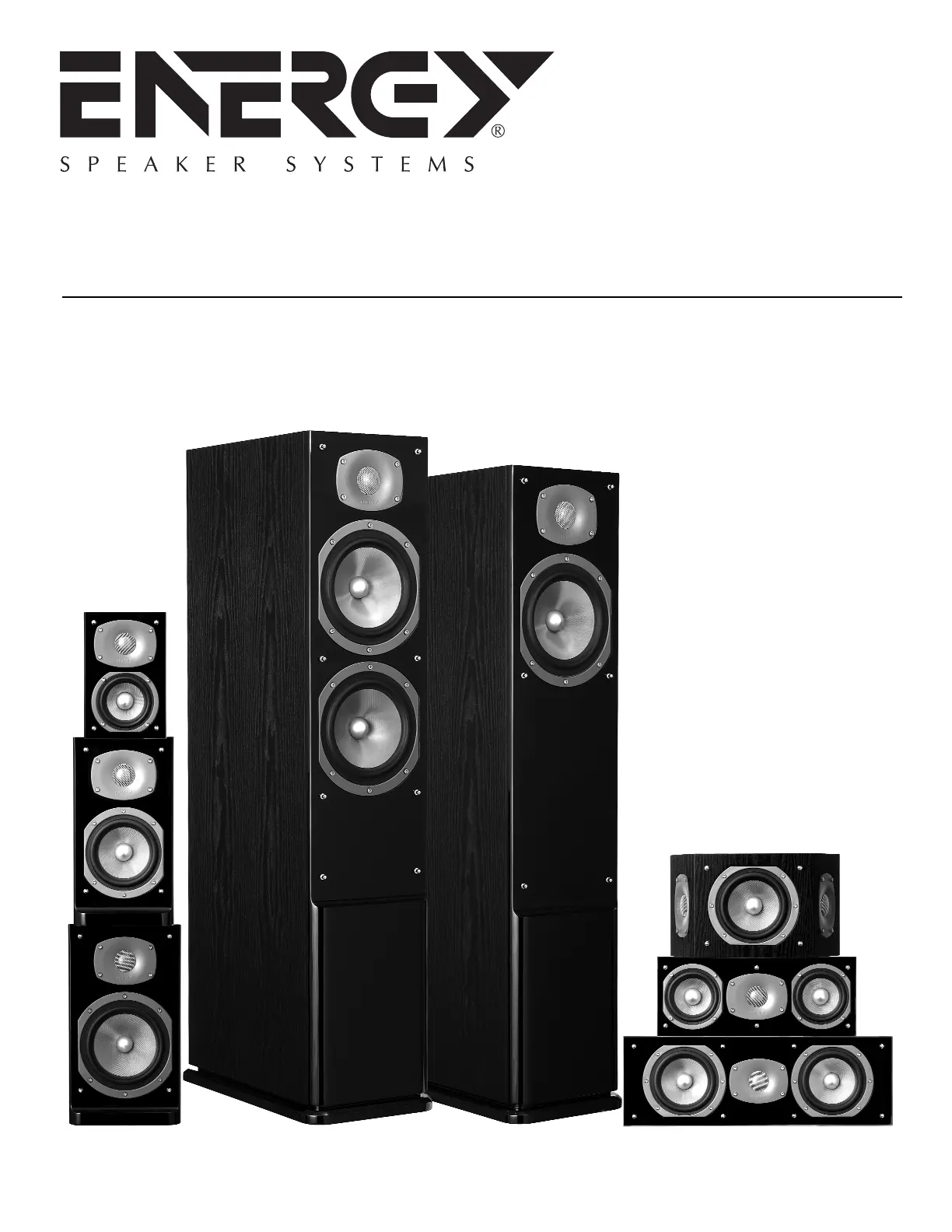
C-50, C-100, C-200,
C-300, C-500, C-C50,
C-C100, C-R100
C-Series
OWNERSMANUAL
Product specificaties
| Merk: | Energy |
| Categorie: | Speaker |
| Model: | C-500 |
Heb je hulp nodig?
Als je hulp nodig hebt met Energy C-500 stel dan hieronder een vraag en andere gebruikers zullen je antwoorden
Handleiding Speaker Energy

18 Augustus 2023
17 Augustus 2023
17 Augustus 2023
17 Augustus 2023
17 Augustus 2023
17 Augustus 2023
17 Augustus 2023
17 Augustus 2023
17 Augustus 2023
Handleiding Speaker
Nieuwste handleidingen voor Speaker
17 Juni 2026
17 Juni 2026
17 Juni 2026
17 Juni 2026
16 Juni 2026
16 Juni 2026
16 Juni 2026
16 Juni 2026
16 Juni 2026
16 Juni 2026