Emko Eco PID Handleiding
Emko Temperatuurregelaar Eco PID
Bekijk gratis de handleiding van Emko Eco PID (2 pagina’s), behorend tot de categorie Temperatuurregelaar. Deze gids werd als nuttig beoordeeld door 137 mensen en kreeg gemiddeld 5.0 sterren uit 2 reviews. Heb je een vraag over Emko Eco PID of wil je andere gebruikers van dit product iets vragen? Stel een vraag
Pagina 1/2
3
2
1
PO1
AL2
°C
°F
/
Eco
PO2
AL1
PO1
AL2
°C
°F
/
Eco
PO2
AL1
4
5
6
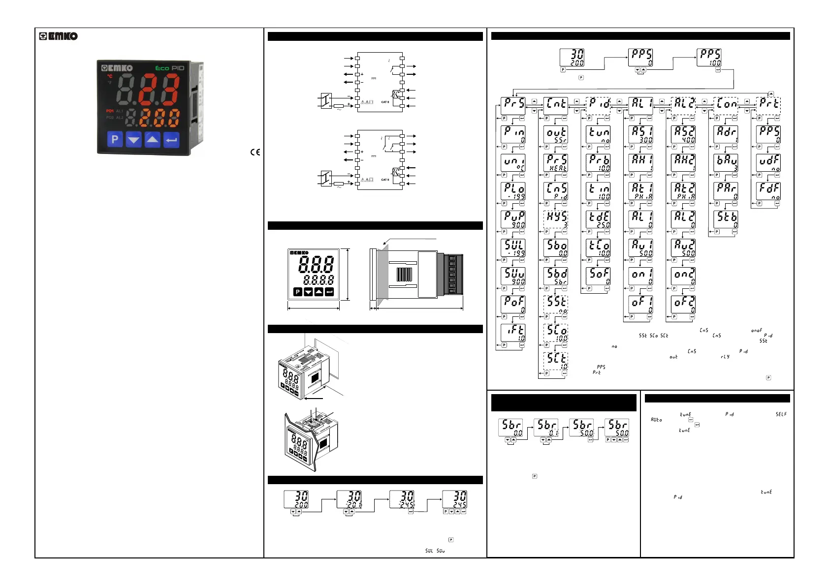
Eco PID, PID Temperature Control Un�t
- 3 d�g�t process (PV) and 4 d�g�t set (SV) d�splay
- Temperature sensor�nput (TC,RTD)
- Programmable ON/OFF, P, PI, PD and PID control forms
- Adaptat�on of PID Coeff�c�ents to the system w�th Self-Tune and Auto-Tune
- Programmable Heat�ng or Cool�ng Funct�ons for Control Output
- Selectable Alarm Funct�ons for Alarm Output
- Ser�al RS485 Commun�cat�on (opt�onal)
Introduct�on Brochure. ENG EcoPID 01 V04 10/19
Easy Access D�agram For Program Parameters
Panel Mount�ng
Enter Password w�th �ncrement
or decrement buttons.
Approve password
w�th Enter button
Ma�n ScreenPassword Screen
Eco ser�es temperature controllers are des�gned for measur�ng and controll�ng a
temperature value. They can be used �n many appl�cat�ons w�th the�r TC and RTD
temperature measurement �nput, mult�-funct�on control outputs, selectable alarm
funct�ons.
They are ma�nly used �n glass, plast�c, petro-chem�stry, text�le, automot�ve and mach�ne
product�on �ndustr�es. Accurate and advanced controll�ng �s performed w�th selectable
ON-OFF, P, PI, PD, PID and Self Tune/Auto Tune PID funct�ons.
SPECIFICATIONS
Process Input: Thermocouple (TC): J, K, R, S, T and L (IEC584.1)(ITS90)
Thermores�stance (RTD): Cu-50 and PT-100 (IEC751)(ITS90)
Measurement Range: Please refer to process �nput type select�on �n process menu
parameters sect�on.
Accuracy:
Thermocouple (TC):( ± 0.25% of full scale or ± 3ºC, wh�ch one �s greater) ±1 d�g�t max.
Thermores�stance (RTD):( ± 0.25% of full scale or ± 2ºC, wh�ch one �s greater) ±1 d�g�t
max.
Cold Junct�on Compensat�on:Automat�cally ±0.1°C/1°C
L�ne Compensat�on:Max�mum 10 Ohm
Sensor Break Protect�on:Upscale
Sampl�ng Cycle: 0.1 second
Input F�lter:Programmable
Control Form: ON/OFF, P, PI, PD or PID (Control form can be programmed by the user)
OUTPUT
Process Output:Relay (5A@250VV at res�st�ve load) or SSR Dr�ver Output
(Max�mum 10mA, Max. 12VZ )
Alarm Output:Relay (5A@250VV at res�st�ve load)
SUPPLY VOLTAGE (It must be determ�ned �n order)
230VV (±15%) 50/60Hz - 2VA
115VV (±15%) 50/60Hz - 2VA
100-240VV 50/60Hz - 2VA
24VV(±%15) 50/60Hz - 2VA
24VW (±%15) 50/60Hz - 2VA
10...30VZ - 2W
DISPLAY
Process D�splay:16 mm Red 3 d�g�t LED D�splay
Set Value D�splay:9 mm Orange 4 d�g�t LED D�splay
Led Ind�cators:PO1 (SSR Process Output Status Led), PO2 (Relay
Process Output Status Led), AL1, AL2 (Alarm Output Status Leds),
ºC, ºF LEDs
ENVIRONMENTAL RATINGS and PHYSICAL SPECIFICATIONS
Operat�ng Temperature:0...50ºC
Hum�d�ty :0-90%RH (none condens�ng)
Protect�on Class: IP65 at front, IP20 at rear
We�ght:150 gr.
D�mens�on:48 x 48 mm, Depth: 86,5 mm
Panel CutOut:46 x 46 mm
*1 - ON/OFF Hysteres�s parameter �s not act�ve unless parameter �s set as .
*2 - Soft Start parameters( , , ) �s not act�ve unless parameter �s set as .
*3 - Soft Start Control Output and Soft Start Control T�me parameters �s not act�ve �f parameter
�s set as .
*4 - PID control parameters are not act�ve unless parameter �s set as .
*5 -Alarm-2 parameters are not act�ve �f parameter �s set as .
*6 - Commun�cat�on parameters are not act�ve on dev�ces have no commun�cat�on module.
*7 - If �s d�fferent from 0 and user enters to program menu w�thout enter�ng the password
P
rot menu �s not shown.
Note: User can ex�t from any parameter screen w�thout sav�ng the values by press�ng button. If
no operat�on for 120 seconds, dev�ce automat�cally return to ma�n screen.
Easy Access D�agram For Sensor Break Output
Value From Ma�n Screen
Change the sensor break
output value w�th �ncrement
or decrement buttons.
Press Enter button to save
new sensor break output value
and ex�t.
PO2
PO1
AL1
AL2
°C
°F
/
Ma�n Screen
PO2
PO1
AL1
AL2
°C
°F
/
PO2
PO1
AL1
AL2
°C
°F
/PO2
PO1
AL1
AL2
°C
°F
/
Ma�n Screen
Note1: User can ex�t from parameter screen w�thout sav�ng the
values by press�ng button. If no operat�on for 120 seconds, dev�ce
automat�cally ex�ts from parameter screen.
Note2: Sensor break output value can be adjusted on programm�ng
sect�on too.
Tune Operat�on
Start�ng the Tune operat�on
1- Enter to the parameter �n menu and select
or ,then press button for sav�ng parameter and turn to ma�n
screen. Or eas�ly press button for 3 seconds* �n ma�n screen.
2- Observe that bl�nks �n set d�splay.
*Only Auto tune can be started by th�s way.
Cancel�ng Tune operat�on:
1- If sensor breaks;
2- If tune operat�on can not be completed �n 8 hours;
3- Wh�le heat�ng self tune �s runn�ng, �f process value becomes
greater than process set value;
4- Wh�le cool�ngself tune �s runn�ng, �f process value becomes less
than process set value;
5- Wh�le tune operat�on �s runn�ng, �f user changes the process set
value;
6- Wh�le tune operat�on �s runn�ng, �f user changes the
parameter �n menu;
Then tune operat�on �s canceled, dev�ce cont�nues to run w�th former
PID parameters w�thout chang�ng PID parameters.
PID TEMPERATURE CONTROL UNIT
PID
Eco
D�mens�ons
PO2
PO1
AL1
AL2
°C
°F
/
PID
Eco
48 mm / 1.89 �nch
48 mm / 1.89 �nch
6 mm / 0.24 �nch
80,52 mm / 3.17 �nch
Max�mum 9 mm / 0.35 �nch
1-Before mount�ng the dev�ce �n your panel,
make sure that the cutout �s of the r�ght s�ze.
2- Check front panel gasket pos�t�on.
3-Insert the dev�ce through the cutout. If the
mount�ng clamps are on the un�t, put out them
before�nsert�ng the un�t to the panel.
4-Insert the mount�ng clamps to the two of
des�gnated holes that located four s�des of
dev�ce.
5-Drag the mount�ng clamps �n d�rect�on 5
unt�l the dev�ce completely �mmob�le w�th�n the
panel.
6-In order to remove dev�ce push on the
mount�ng clamp as shown w�th arrow 6 and
pull back.
Access and Change Set Values
Press �ncrement or decrement
button to change process set value.
Press Enter button to save new
set value and return the ma�n screen.
Ma�n Screen
PO2
PO1
AL1
AL2
°C
°F
/
PO2
PO1
AL1
AL2
°C
°F
/
Ma�n Screen
PO2
PO1
AL1
AL2
°C
°F
/PO2
PO1
AL1
AL2
°C
°F
/
Temperature Set Value Parameter (Default: 200) MODBUS ADDRESS: 40000
a
Note-1:User can ex�t from set value sect�on w�thout sav�ng the values by press�ng button. If no
operat�on for 120 seconds, dev�ce automat�cally ex�ts from Set Value sect�on.
Note-2: Set value can be adjusted between Set Value Low and H�gh L�m�t ( - ).
PO2
PO1
AL1
AL2
°C
°F
/
PO2
PO1
AL1
AL2
°C
°F
/
PO2
PO1
AL1
AL2
°C
°F
/
PO2
PO1
AL1
AL2
°C
°F
/
PO2
PO1
AL1
AL2
°C
°F
/
PO2
PO1
AL1
AL2
°C
°F
/
PO2
PO1
AL1
AL2
°C
°F
/
PO2
PO1
AL1
AL2
°C
°F
/
PO2
PO1
AL1
AL2
°C
°F
/
PO2
PO1
AL1
AL2
°C
°F
/
PO2
PO1
AL1
AL2
°C
°F
/PO2
PO1
AL1
AL2
°C
°F
/
PO2
PO1
AL1
AL2
°C
°F
/
PO2
PO1
AL1
AL2
°C
°F
/
PO2
PO1
AL1
AL2
°C
°F
/
*1
PO2
PO1
AL1
AL2
°C
°F
/
PO2
PO1
AL1
AL2
°C
°F
/
PO2
PO1
AL1
AL2
°C
°F
/
PO2
PO1
AL1
AL2
°C
°F
/
PO2
PO1
AL1
AL2
°C
°F
/
PO2
PO1
AL1
AL2
°C
°F
/
PO2
PO1
AL1
AL2
°C
°F
/
PO2
PO1
AL1
AL2
°C
°F
/
PO2
PO1
AL1
AL2
°C
°F
/
PO2
PO1
AL1
AL2
°C
°F
/
PO2
PO1
AL1
AL2
°C
°F
/
PO2
PO1
AL1
AL2
°C
°F
/
PO2
PO1
AL1
AL2
°C
°F
/
PO2
PO1
AL1
AL2
°C
°F
/
PO2
PO1
AL1
AL2
°C
°F
/
PO2
PO1
AL1
AL2
°C
°F
/
PO2
PO1
AL1
AL2
°C
°F
/
PO2
PO1
AL1
AL2
°C
°F
/
PO2
PO1
AL1
AL2
°C
°F
/
PO2
PO1
AL1
AL2
°C
°F
/
PO2
PO1
AL1
AL2
°C
°F
/
PO2
PO1
AL1
AL2
°C
°F
/
PO2
PO1
AL1
AL2
°C
°F
/
*5
*2
PO2
PO1
AL1
AL2
°C
°F
/
PO2
PO1
AL1
AL2
°C
°F
/
PO2
PO1
AL1
AL2
°C
°F
/
PO2
PO1
AL1
AL2
°C
°F
/
PO2
PO1
AL1
AL2
°C
°F
/
PO2
PO1
AL1
AL2
°C
°F
/
PO2
PO1
AL1
AL2
°C
°F
/
*4
*2,3
*2,3
PO2
PO1
AL1
AL2
°C
°F
/
PO2
PO1
AL1
AL2
°C
°F
/
PO2
PO1
AL1
AL2
°C
°F
/
PO2
PO1
AL1
AL2
°C
°F
/
*7
PO2
PO1
AL1
AL2
°C
°F
/
PO2
PO1
AL1
AL2
°C
°F
/
PO2
PO1
AL1
AL2
°C
°F
/
PO2
PO1
AL1
AL2
°C
°F
/
*6
PO2
PO1
AL1
AL2
°C
°F
/
Press Program button
to access password screen.
Electr�cal W�r�ngs
The Dev�ce w�th One Relay:
The Dev�ce w�th Two Relays:
To reduce the effect of electr�cal no�se on dev�ce, low voltage l�ne (espec�ally sensor
�nput cable) w�r�ng must be separetely from h�gh current and voltage l�ne.If poss�ble,
use sh�elded cable and sh�eld must be connected to ground only one s�de.
c
1
2
3
4
5
6
7
8
9
10
11
12
13
14
PO1
(Process Output 1)
SSR Output
12V
Max. 10mA
C
NO
AL1 / PO2
(Alarm Output 1 or
Process Output 2)
Process
Input
5A@250V
Ser�al Commun�cat�on
(RS485, Modbus RTU)
A+
B-
PID
Eco
PT-100
TC
Supply
Sw�tch
L
N
Supply
Voltage
1A T
Fuse
1
2
3
4
5
6
7
8
9
10
11
12
13
14
PO1
(Process Output 1)
SSR Output
12V
Max. 10mA
C
NO
NO
AL1
(Alarm Output 1)
AL2 / PO2
(Alarm Output 2 or
Process Output 2)
Process
Input
5A@250V
5A@250V
Ser�al Commun�cat�on
(RS485, Modbus RTU)
A+
B-
PID
Eco
PT-100
TC
Supply
Sw�tch
L
N
Supply
Voltage
1A T
Fuse
Product specificaties
| Merk: | Emko |
| Categorie: | Temperatuurregelaar |
| Model: | Eco PID |
Heb je hulp nodig?
Als je hulp nodig hebt met Emko Eco PID stel dan hieronder een vraag en andere gebruikers zullen je antwoorden
Handleiding Temperatuurregelaar Emko

26 Februari 2024
26 Februari 2024
26 Februari 2024
26 Februari 2024
7 Februari 2024
27 November 2023
27 November 2023
27 November 2023
27 November 2023
27 November 2023
Handleiding Temperatuurregelaar
Nieuwste handleidingen voor Temperatuurregelaar
8 Januari 2026
9 December 2025
3 December 2025
3 Oktober 2025
29 September 2025
29 September 2025
18 September 2025
7 Juli 2025
7 Juli 2025
7 Juli 2025