Emerson 1F83H-21NP Handleiding

Emerson Thermostaten 1F83H-21NP

Lees hieronder de đź“– handleiding in het Nederlandse voor Emerson 1F83H-21NP (12 pagina's) in de categorie Thermostaten. Deze handleiding was nuttig voor 22 personen en werd door 2 gebruikers gemiddeld met 4.5 sterren beoordeeld

Pagina 1/12
PART NO. 37-7569
1504
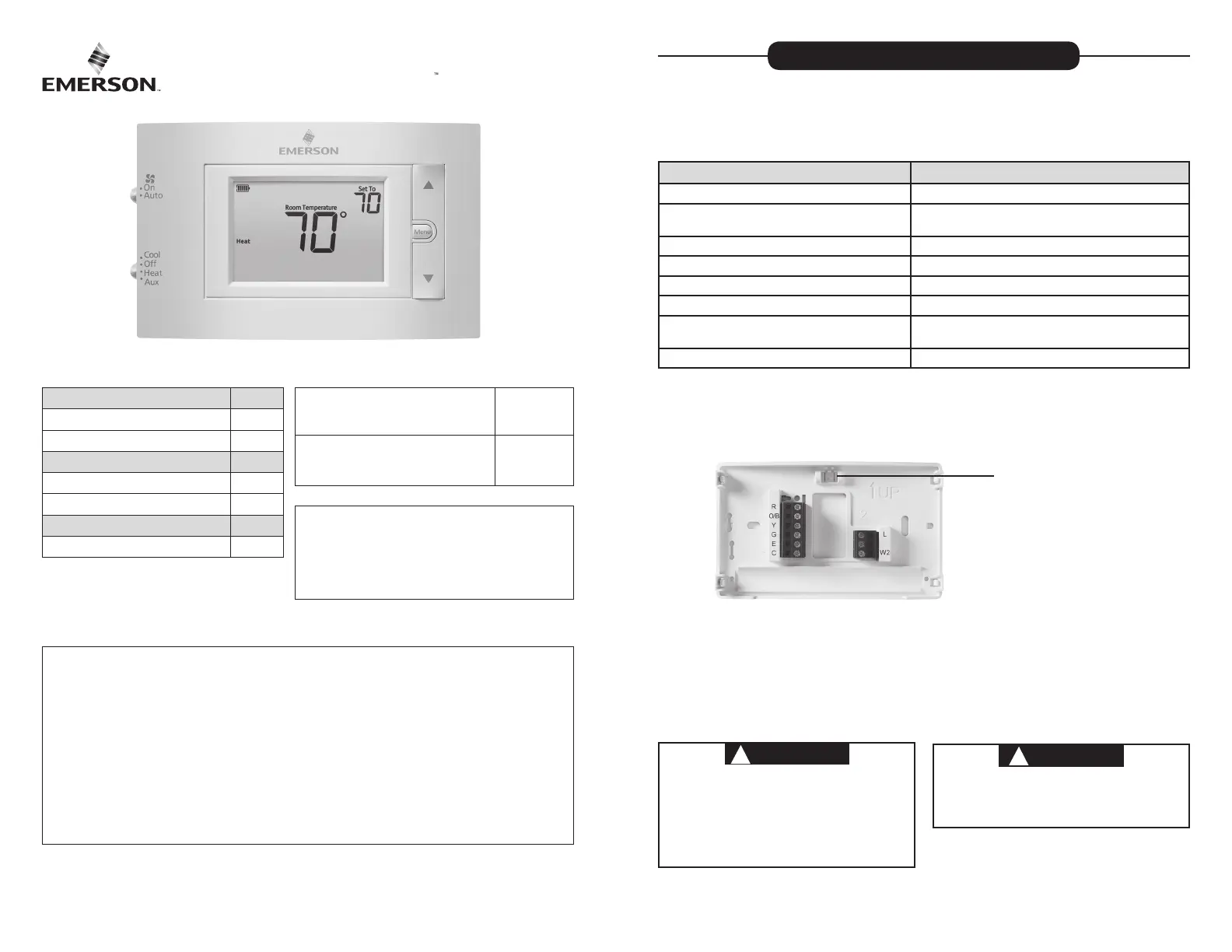
1F83H-21NP (Non-Programmable)
Installation and Operating Instructions
80 Series Heat Pump Thermostat
Battery Powered or Hardwired with Common
emersonthermostats.com
white-rodgers.com
Thermostat Applications
Maximum
Stages
Heat /Cool
Single Stage Compressor, Heat Pump
Systems (air source or geothermal) –
1 Stage Aux/Emergency Heat
2/1
Thermostat Installation 2-4
Wiring 2
Installer Menu 3-4
Using the Thermostat 5-6
Thermostat Overview 5
User Menu 6
Troubleshooting 7-8
Homeowner Help Line 8
INDEX
MERCURY NOTICE: This product does not contain
mercury. However, this product may replace a product
that contains mercury. Mercury and products containing
mercury must not be discarded in household trash.
Refer to www.thermostat-recycle.org for information
on disposing of products containing mercury.
Electrical Rating:
Battery Power to VAC, NEC Class II, Hz ..................................... 20 30 50/60
Input-Hardwire to VAC, NEC Class II, / Hz .................................... 20 30 50 60
Terminal Load A per terminal, A maximum all terminals combined .......................................... 1.5 2.5
Setpoint Range to F ( to ........................................ 45° 99° 7° 37° C)
Rated Dierentials (@ 6°F/ Hr): Fast Med Slow
Heat Pump (Heat)................................ 0.9°F 1.2°F 1.7°F
Heat Pump (Cool) . ................................ 0 9°F 1.2°F 1.7°F
Auxiliary Heat . ...................................... 0 5°F 0.75°F 1.9°F
Operating Ambient .................................. 32°F to +105°F (0° to +41°C)
Display Temperature Range 32°F to +99°F (0 to 37°C) .......................
Operating Humidity % non-condensing maximum ................................. 90
Shipping Temperature Range ................... °F to + °F-20 150 (-29° to +65°C)
Thermostat Dimensions ........................... 3-3/4” H x 6” W x 1-1/8” D
SPECIFICATIONS
Optional Accessory: Wall Cover-up Plate F61-2663, 6 3/4” W x 4 1/2” H
2
Terminal Designations Terminal Function
RPower ( V) 24
O/B Changeover Terminal-Energized in Cool (O) or Heat (B)
for Heat Pump or Damper Systems
Y Heat and Cool Mode 1st Stage Compressor
G Fan Relay
E* Auxiliary only Heat Mode (Emergency Heat)
C Common wire for (optional with batteries)24V
LHeat Pump malfunction / Diagnostic terminal
(input signal requires common)
W * Heat Mode – nd stage2 2
*Cut W2/E jumper when separate heat sources are used for W and E.2
IMPORTANT: For Dual Fuel Heat Pump applications, be sure to turn on the Duel Fuel Logic option
(found in the Installer’s Menu)
WIRING
Refer to equipment manufacturer’s instructions for specic system wiring information. After
wiring, see INSTALLER MENU for proper thermostat conguration. Wiring table shown are
for typical systems and describe the thermostat terminal functions.
THERMOSTAT INSTALLATION
Precautions
• Do not exceed the specication ratings.
• All wiring must conform to local and national electrical codes and ordinances.
• This control is a precision instrument, and should be handled carefully. Rough handing or
distorting components could cause the control to malfunction.
WARNING
!
Do not use on circuits exceeding specied voltage.
Higher voltage will damage control and could
cause shock or re hazard.
Do not short out terminals on gas valve or primary
control to test. Short or incorrect wiring will burn
out thermostat and could cause personal injury
and/or property damage.
CAUTION
!
To prevent electrical shock and/or equipment
damage, disconnect electrical power to system
at main fuse or circuit breaker box until
installation is complete.
Leveling Thermostat
Leveling is for appearance only and
will not aect thermostat operation.
3
INSTALLER MENU
To prevent changes that may aect system performance, this thermostat has an INSTALLER’S
MENU and a USER MENU. The INSTALLER’S MENU provides access to every option, while the
USER MENU provides access to items that will not aect system performance. To access the
INSTALLER’S MENU press the button for 8 seconds. The display will show item Menu 30 in
the table below. Use to navigate through menu items. Press or to change a menu Next
setting.
Installer’s Menu #
(Hold Menu 8 Seconds) Description Default Setting
(ashing icons)
Settings
(Press or )
30 Heat Cycle Rate (how often
the heat will turn on) MEd
SLO – slow
MEd – medium
FAS – fast
32 Aux Cycle Rate (how often the
auxiliary heat will turn on) MEd
SLO – slow
MEd – medium
FAS – fast
35 Cool Cycle Rate (how often
the cooling will turn on) MEd
SLO – slow
MEd – medium
FAS – fast
50 Compressor Lockout
(protects the compressor
from short cycling)
OFF On – minute delay 5
OFF – no delay
60 Duel Fuel Logic (turn On when using
gas as the auxiliary heat source) OFF On- gas auxiliary heat
OFF- electric auxiliary heat
65 Maximum Heat Limit
(maximum set point for heat mode) 99 47 99to
66 Minimum Cool Limit
(minimum set point for cool mode) 45 45 97to
(Installer Menu continued on next page)
1.) W2/E Jumper Wire
This thermostat electrically connect the W and E terminals so that you do not need to 2
do this with a jumper wire. If your system has separate W and E wires, clip the W /E 2 2
jumper located on the back of the thermostat. This will isolate both terminals so they can
be used independently.
2.) O/B Terminal Switch
The O/B switch on this thermostat is factory set to the position. This will accommodate O
the majority of heat pump applications, which require the changeover relay to be
energized in . If the heat pump being installed requires a terminal to energize the Cool B
changeover relay in , the O/B switch must be moved to the position. Heat B
Baery Locaon
Premium AA alkaline batteries
are required when C-wire is
not available. When C-wire is
available, the batteries provide
a back-up source of power (this
will maintain the clock in the
event of a power outage).
1
2
4
CAUTION
!
To prevent compressor and/or property damage, if the outdoor temperature is below 50°F,
DO NOT operate the cooling system.
Do not allow the compressor to run unless the compressor oil heaters have been operational
for hours and the system has not been operational for at least minutes. 6 5
TEST EQUIPMENT
Turn on power to the system.
Fan Operation
If your system does not have a G terminal connection, skip to . Heating System
1.) Move fan switch to On position. The blower should begin to operate.
2.) Move fan switch to Auto position. The blower should stop immediately.
Heating System
1.) Move System Heat Switch to position. If the auxiliary heating system has a standing
pilot, be sure to light it.
2.) 1° Press to adjust thermostat setting to above room temperature. The heat pump
system should begin to operate and the thermostat will indicate . Heat On
3.) 3° above room temperature. The auxiliary heat Press to adjust thermostat setting to
should begin to operate and the thermostat will indicate .Heat On Auxiliary
4.) 1° Press to adjust thermostat setting below room temperature. The heating system
should stop operating and the thermostat should indicate Heat.
Auxiliary System
1.) Move System Aux Switch to position. If the auxiliary heating system has a standing pilot,
be sure to light it.
2.) Press to adjust thermostat setting to above room temperature. The auxiliary heating 1°
system should begin to operate and the thermostat will indicate Heat On Auxiliary.
3.) 1° Press to adjust thermostat setting below room temperature. The auxiliary heating
system should stop operating and the thermostat should indicate Heat Auxiliary.
Cooling System
1.) Move position. System Switch to Cool
2.) 1° Press to adjust thermostat setting below room temperature. The blower should
come on immediately on high speed, followed by cold air circulation. The thermostat will
indicate There can be up to a minute delay. (see INSTALLER MENU, item Cool On. 5 50)
3.) 1° Press to adjust thermostat setting to above room temperature. The cooling system
should stop operating and the thermostat will indicate Cool.
Note: If is shown on the display, the compressor lockout feature is operating. Starting Soon
There will be up to a minute delay before the compressor turns on.(see INSTALLER MENU, 5
item )50
Installer’s Menu #
(Hold Menu 8 Seconds) Description Default Setting
(ashing icons)
Settings
(Press or )
79 Fahrenheit or Celsius °F °F – Fahrenheit
°C – Celsius
81
Temperature Display Adjustment
(adjust the displayed “Room
Temperature”)
0-5 to +5
83 Continuous Display Light (keep
the backlight always on – “C” wire
required)
OFF On – always on
OFF – momentarily
99 Keypad Lock (prevent unwanted
changes to the thermostat) OFF On – disable buttons
OFF – all buttons are active
INSTALLER MENU (C0ntinued)
5
THERMOSTAT OVERVIEW
Before you begin using your thermostat, you should be familiar with its features, display and
the location/operation of the thermostat buttons and switches.
THERMOSTAT BUTTONS
AND SWITCHES THE DISPLAY
1. 7.)) Fan Switch Thermostat is protecting the equipment from short cycling
( minute delay)5-
2 8.).) System Switch Indicates that the system is running in cool, heat or auxiliary
mode (The auxiliary will run in Heat mode when the heat
pump cannot maintain the set temperature.)
3.) Backlight Button (located on the top
of the thermostat
9.) Battery status indicator
4.) Raises Temperature Setting 10.) Low battery indicator
5 11.) .) Access Menu Options Temperature setpoint
6.) Lowers Temperature Setting 12.) Appears when the keypad is locked (to prevent unwanted
changes)
13.) is used to advance through the menuNext (Menu button)
14.) SEE TROUBLESHOOTING
1
2
3
4
5
6
7
8
9 10 11
12
13
14
USING THE THERMOSTAT
Whenever “ Replace ” appears in the display, new premium brand AA alkaline batteries
should be installed. If the house will be unoccupied for an extended period and either “ ”
or “ Replace
” is displayed, install new batteries before leaving.
6
USER MENU
To customize thermostat settings, press the button from the home screen. Menu
Use to advance through menu items. Press or to change the setting. Next
User’s Menu #
(Press Menu button
and release)
Description Default Setting
(ashing icons)
Settings
(Press or )
01 Fahrenheit or Celsius °F °F – Fahrenheit
°C – Celsius
02 Temperature Display
Adjustment (adjust the Room
Temperature)
0 -5 to +5
03
Continuous Display Light
(keep the backlight always on –
“C” wire required)
OFF On – always on
OFF – momentarily
04 Keypad Lock (prevent unwant-
ed changes to the thermostat) OFF On – disable buttons
OFF – all buttons are active
• Keypad Lockout – To prevent unwanted changes, the buttons can be disabled.
To turn this feature On, press and hold and the button Menu unl the icon appears
(this can also be turned on in the menu). To turn O, press and hold and the Menu
button for seconds. 3


Product specificaties

Merk: Emerson
Categorie: Thermostaten
Model: 1F83H-21NP

Heb je hulp nodig?

Als je hulp nodig hebt met Emerson 1F83H-21NP stel dan hieronder een vraag en andere gebruikers zullen je antwoorden