Elcom REQ024X Handleiding
Elcom Niet gecategoriseerd REQ024X
Bekijk gratis de handleiding van Elcom REQ024X (2 pagina’s), behorend tot de categorie Niet gecategoriseerd. Deze gids werd als nuttig beoordeeld door 18 mensen en kreeg gemiddeld 4.5 sterren uit 6 reviews. Heb je een vraag over Elcom REQ024X of wil je andere gebruikers van dit product iets vragen? Stel een vraag
Pagina 1/2
010302
REQ0..X, REQ1..X, REV1...X
Door station AUDIO 2wire
z
6LE000691B
z
Safety instructions
Electrical equipment may only be installed and
assembled by a qualifi ed electrician in accord-
ance with the relevant installation standards,
guidelines, regulations, directives, safety and
accident prevention regulations of the country.
When installing and laying cables, always com-
ply with the applicable regulations and stand-
ards for SELV electrical circuits.
These instructions are an integral component
of the product and must be retained by the end
user.
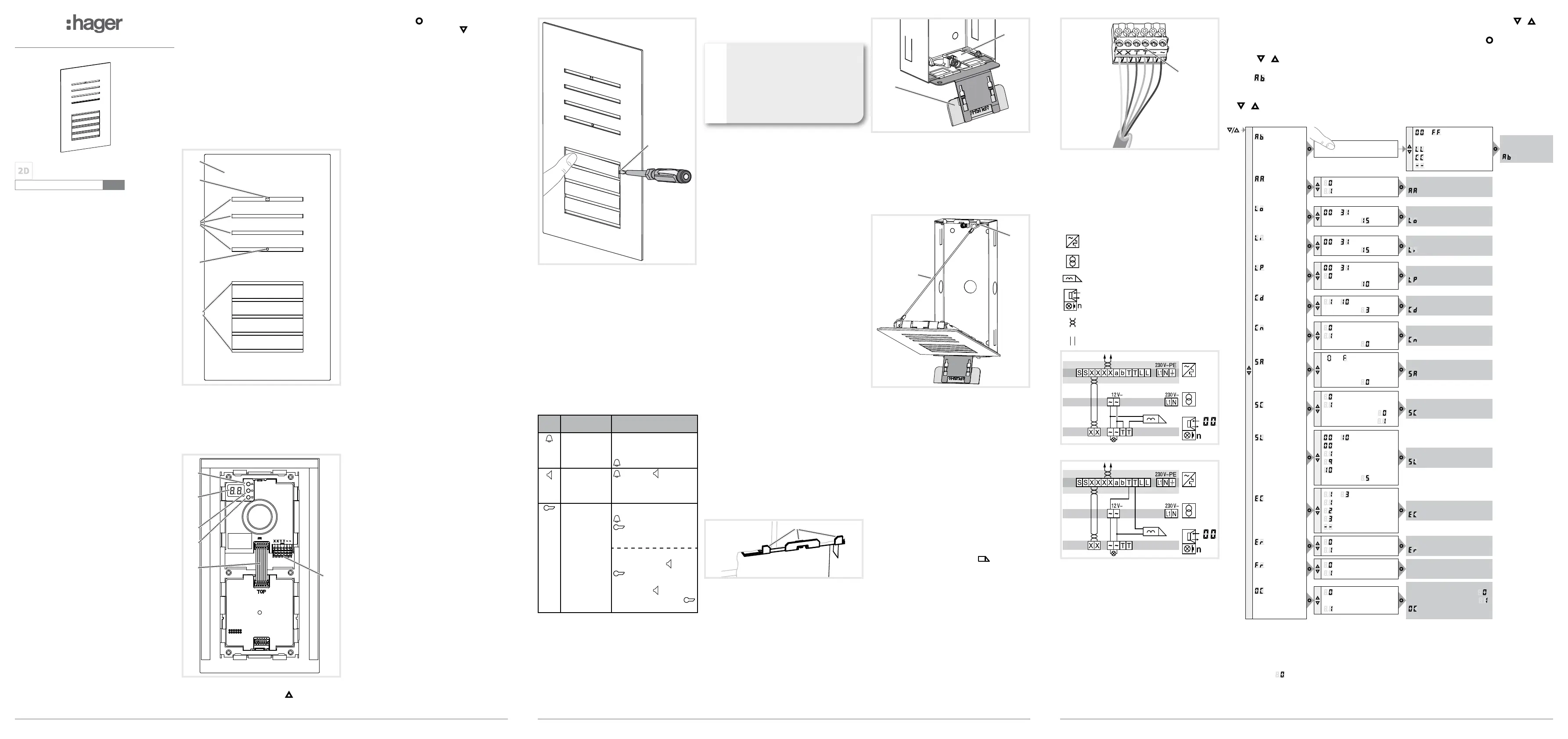
Design and layout of the device
(5)
(4)
(1)
(2)
(3)
(6)
Figure 1: Design and layout of the device front
(1) Front plate stainless steel
(2) Microphone
(3) Door loudspeaker
(4) Twilight sensor for call button
(5) Button panel with call push-buttons
(6) Cover strip for dismantling protection
(10)
(7)
(8)
(9)
TOP
(11)
(12)
Figure 2: Design and layout of the device back
(7) Adjustment button Upwards
(8) 7-segment display
(9) Selection button
(10) Adjustment button downwards
(11) Module bus connector
(12) Connection terminal block
Function
The audio door station works in the 2wire bus sys-
tem and enables communication via sound.
Correct use
-for surface- or ush-mounted installation
-not compatible with intercom systems of other
manufacturers
-suitable for use exterior applications
Product characteristics
-completely pre-assembled
-protected against vandalism
-with brushed 2 mm stainless steel front plate
-Name plate can be changed from the front with-
out any special tools
-One-man commissioning
-call button with acknowledge tone (can be
switched off) and tactile feedback
-call button, light release or door release can be
adjusted even without any function
-durable, homogeneous, white LED call
push-button backlighting
-Twilight controlled call push-button backlighting
with adjustable switch-on brightness level
-Opening of door station only with enclosed
opening tool
-break-proof ush-mounted call buttons
-Loudspeaker and microphone protected against
sabotage
-Volume and microphone sensitivity settable
-Door release contact on 1 ... 10 s adjustable
-Door release without previous call adjustable in
single door systems
-Safety rope as installation aid
Operation
Establish call (ringing)
zPress the call push-button assigned to the
desired subscriber.
If con gured, the call push-button activation is
con rmed by an acknowledge tone. Addressed
indoor stations are called.
Switch-on lights
A call push-button is con gured and labelled for
lighting control (light insert supplied).
zPress the call push-button for lighting.
zIf con gured, the call push-button activation is
con rmed by an acknowledge tone. The light
contact of a line power supply is closed for the
set time.
Label call push-button
zKeep call push-button pressed on one side.
On the opposite side, the lever opening (14) is
accessible for a screwdriver.
zPosition the screwdriver in the lever opening
(13) and release the interlock (Figure 3).
zRemove cover with name plate insert.
(13)
Figure 3: name plate change
(13) Lever opening
zLabel name plate insert if required.
zInsert name plate insert, prepared foil or pre-
pared labelling strip into the cover and press on
cover.
Do not use any paper for the name plate insert,
since moisture and UV light will damage the
paper and labelling.
UV-resistant foil with laser printing is suitable
for labelling as well as labelling devices for
labelling strip:
- small buttons - 12 mm
- medium buttons - 30 mm
Door stations with status indication
Dis-
play
CauseFunction/Lighting
duration
A subscriber is
called.
After 90 s without call
acceptance or an opera-
tion on the door station,
goes out.
A subscriber
accepts the
door call.
goes out, lights up
as long as the intercom
connection is pressed
down, max. 3 min.
The door is
unlocked.
Call not accepted:
Symbol goes out and
lights up for the un-
locking time set on the
door station.
Call accepted:
In addition to the
,
the
lights up for the un-
locking time set on the
door station.
goes out
approx. 5 sec after the
symbol.
Table 1: Status indications of door station
Cleaning and care
Commercially available products for stainless
steel and car paintwork care containing a wax
component for conservation are recommended for
cleaning and care.
Do not use wire wool, wire brushes or any
similar products for cleaning. This will prevent
damage to the surface and accumulation of
ash rust.
P
P
P
Information for electricians
Installation and electrical connection
DANGER!
Touching live parts in the installation
environment can result in an electric
shock!
An electric shock can be lethal!
Before working on the device or load,
disconnect all associated circuit brea-
kers. Cover all live parts in the area!
ç
When installing door communication systems,
comply with the general safety regulations for tele-
communications systems according to VDE 0800:
-Separate routing of power and door communi-
cation cables with a minimum spacing of 10 cm
-Partitions between power and door communica-
tion cables in shared trunkings
-Use of standard telecommunications' cables, e.
g. J-Y (St) Y with 0.8 mm diameter
Bus cables
-J-Y(ST)Y or A-2Y(L)2Y
Use wrapped wire pair.
Recommendation: white/yellow
-CAT
Use wrapped wire pair
Recommendation orange/white.
Avoid interference!
The 13-MHz video carrier frequency used for
two-wire video door communication systems
can cause reciprocal interference with other
devices, such as radios, routers and WLAN
devices.
zOnly use shielded cables corresponding to
the qualities recommended in this manual.
zIt is essential to comply with the applicable
regulations during planning and installation.
zRoute cables, wire the devices, and in
particular implement shielding and earthing
measures as described below.
Mounting door station
Surface-mounted or ush-mounted housing is
installed (see Assembly instruction housing).
The connection cables and indoor stations are
connected to the line power supply while taking
the maximum cable lengths and attenuations into
account (see operating instructions of the line power
supply).
zThe fastening elements supplied with the
ush-mounted housing must be assembled with
the nuts on the top and bottom on the threaded
bolts. The support bracket (14) of the fastening
elements must be located on the wall surface.
(14)
Figure 4: Support bracket of the fastening elements
(14) Support bracket of the fastening elements
zInsert opening tool (15) into the mounting de-
vice of the lower fastening element (16) on the
housing (Figure 5).
P
(15)
(16)
Figure 5: Inserted opening tool
(15) Opening tool
(16) Fixing element
zAttach the loops of the safety rope (17) to the
upper left suspension of the door station and to
the upper fastening element (18) in the housing.
Place the door station for installation onto the
opening tool (Figure 5).
(18)
(17)
Figure 6: installation position of door station
(17) Safety rope
(18) Upper xing element
Connect door station
zShorten connection cable of the door station as
required and strip the required wires.
zPull off connection terminal block (12) from the
audio insert.
zConnect the wire pair of the 2wire bus cable
to the terminals XX of the connection terminal
block (Figure 8).
zConnect door release to the terminals TT of
the connection terminal block ( gure 7 and 8) if
required.
or:
zFor manipulation-protected installation, connect
the door release to the contact
of the line
power supply (Figure 9).
The door release lead must not be inserted
through the door station in order to protect
against manipulation.
zFor call push-button backlighting connect 12
V~ lead from the power transformer to the
terminals ~~ of the connection terminal block
(Figure 7... 9).
P
(12)
Figure 7: Wired connection terminal block
Information on the connection as a oor door
station can be found in the operating instruc-
tions of the line power supply.
zAttach connection terminal block to audio insert.
Circuit symbols and elements of the circuit
diagrams
Line power supply RMD
Power transformer
Door release
Door station audio
Wrapped wire pair for 2wire devices (recom-
mendation: white/yellow wire pair)
Unwrapped wire pair, for e.g. for door release
Figure 8: Door release connection on the door station
Figure 9: Connection of door station with manipu
lation-protected door release
If interference occurs in telecommunications
systems, radio services or other systems during
the operation of existing video door communication
systems, measures for shielding and earthing the
cables and for ltering must be implemented.
zFor this purpose, connect all of the drain wires
of the cables in a star shape using a terminal.
zConnect all drain wires to the PE rail in the
distribution box.
P
Calling up and navigating system settings
On the back of the audio module, there are 3
buttons and a 2-digit 7-segment display (Figure 2,
7-10) for the system settings 10).
zPress
/ button.
Device turns to setting mode. The rst menu
entry
is displayed.
The reading directions of the 7-segment dis-
play varies by 180° depending on which button
/
you start with.
P
zSelect the desired menu entry with /
( gure 7).
zCon rm the selection with
.
The 7 segments display goes dark if there is no
actuation for 5 seconds. Settings are applied.
The device returns to normal operation.
P
Individual call push-
button address/
function
Confi rm the call push-
button to be set
... =
Call push-button
address
= Light push-button
=
Door release push-but
ton
= no function
Address/Function
saved,
is displayed
Automatic call push-
button addressing
= Cancel
= Start addressing
Addressing executed/cancelled,
is displayed
Door speaker
volume
...
Default setting
Volume set,
is displayed
Microphone
sensitivity
...
Default setting
Sensitivity set.
is displayed
Operating signal
sound volume
...
= Acoustic signal off
Default setting
Volume set,
is displayed
Door release
unlocking time
... Seconds
Default setting
seconds
Unlocking time set,
is displayed
Door release
function
= only with door call
= also without door call
1)
Default setting
Door release function is set,
is displayed
set
door address
x ... x
x = received line
address
Default setting
Door address set,
is displayed
Camera present
= No camera
= with camera
Default setting: Audio
Video
Camera option set,
is displayed
Call push-button
Backlighting
settings
(switch-on
brightness level)
...
= Off
= lowest value
= highest value
= always on
Default setting
Backlighting set,
is displayed
Display error codes
(max. 5 can be
saved)
... Error codes
=
module communication
= sticking call button
= module address
= no error present
Error codes were displayed,
is displayed
Reset error codes
= Cancel
= Reset
Error codes were deleted,
is deleted
factory setting
= Cancel
= Reset
Reset to the factory setting,
indication goes out
Multiple call or
one call
= Multiple call
(factory setting)
= One call
Each key press starts a call
or fi rst ends the current call,
OC is displayed
2
)
.
1)
Door release functions without door call only possible single door systems
2)
OC „one call“, software version 2.0 or higher
Figure 10: Overview of system settings
For installations using RTQ52xx, TJA510N,
TJA470 or multiple door stations,
multiple call
must be used.
P
Product specificaties
| Merk: | Elcom |
| Categorie: | Niet gecategoriseerd |
| Model: | REQ024X |
Heb je hulp nodig?
Als je hulp nodig hebt met Elcom REQ024X stel dan hieronder een vraag en andere gebruikers zullen je antwoorden
Handleiding Niet gecategoriseerd Elcom

17 November 2024
17 November 2024
17 November 2024
8 Februari 2024
7 Februari 2024
7 Februari 2024
7 Februari 2024
7 Februari 2024
7 Februari 2024
7 Februari 2024
Handleiding Niet gecategoriseerd
Nieuwste handleidingen voor Niet gecategoriseerd
23 Juli 2026
23 Juli 2026
23 Juli 2026
23 Juli 2026
23 Juli 2026
22 Juli 2026
22 Juli 2026
22 Juli 2026
22 Juli 2026
22 Juli 2026