Doepke DHS 4-125 NA Handleiding
Doepke Schakelaar DHS 4-125 NA
Bekijk gratis de handleiding van Doepke DHS 4-125 NA (2 pagina’s), behorend tot de categorie Schakelaar. Deze gids werd als nuttig beoordeeld door 50 mensen en kreeg gemiddeld 5.0 sterren uit 2 reviews. Heb je een vraag over Doepke DHS 4-125 NA of wil je andere gebruikers van dit product iets vragen? Stel een vraag
Pagina 1/2
Gewährleistung
Für fachgerecht montierte, unveränderte Geräte gilt ab Kauf durch
den Endverbraucher die gesetzliche Gewährleistungsfrist. Die
Gewährleistung bezieht sich nicht auf Transportschäden sowie Schäden,
die durch Kurzschluss, Überlastung oder bestimmungswidrigen Gebrauch
entstanden sind. Bei Fertigungs- und Materialfehlern, die innerhalb der
Gewährleistungsfrist erkannt werden, leistet unser Werk kostenlos Reparatur
oder Ersatz. Der Gewährleistungsanspruch erlischt, wenn das Gerät
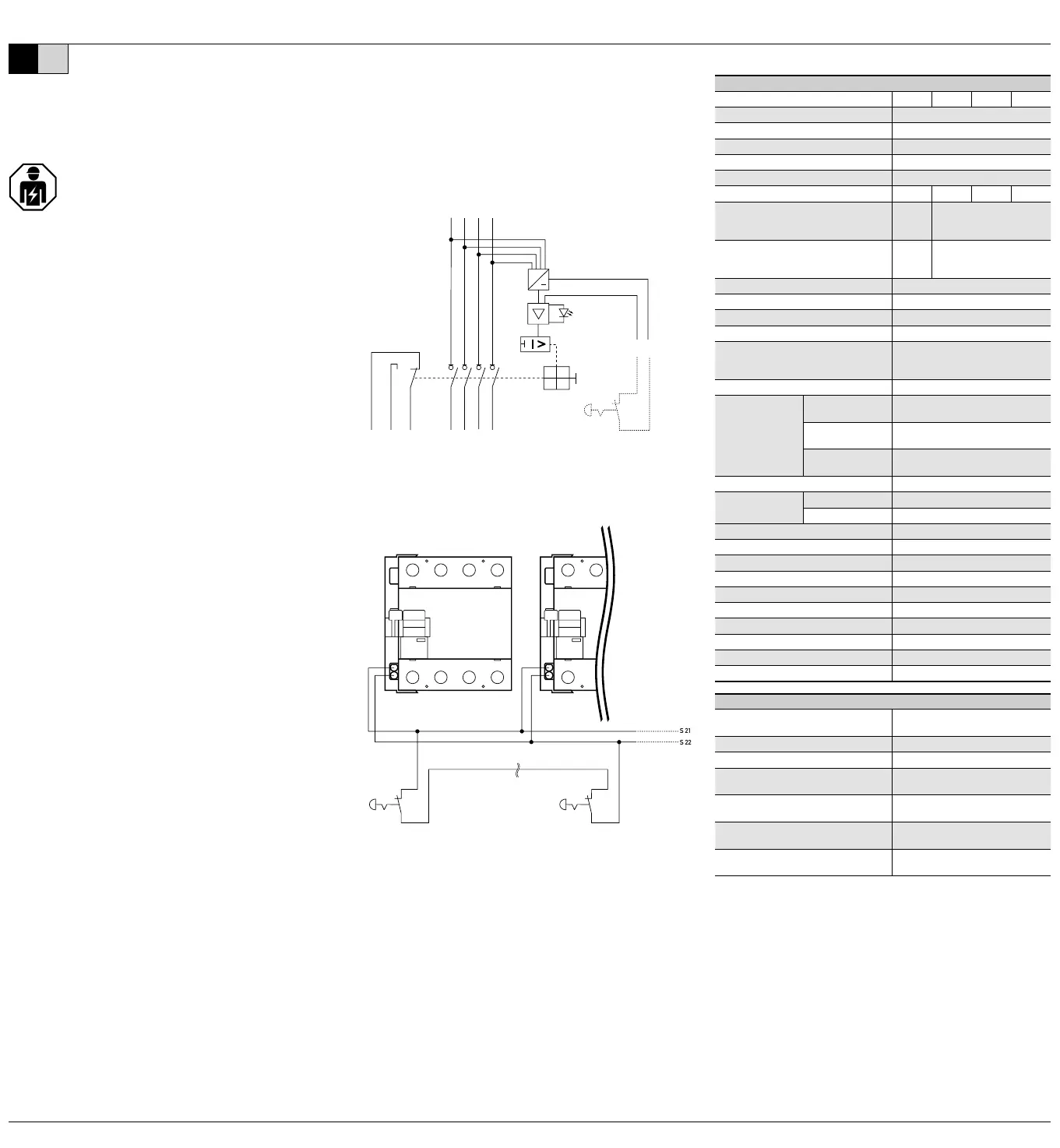
Anschlussschema
N735
8
N
46
~
1214
11
S 21S 22
Not-Aus-Kreis
emergency off circuit
Vvierpolig, N links
S 21
S 22
VAnschluss mehrerer DHS 4 NA über einen Not-Aus-Kreis
Montage- und Bedienungsanleitung
für Lasttrennschalter
der Baureihe DHS 4 NA
Diese Montage- und Bedienungsanleitung richtet sich an die
Elektrofachkraft. Aufgrund erheblicher Gefährdungspotenziale ist
der Einbau von Geräten dieser Art nicht für den elektrotechnischen
Laien geeignet. Die Montage- und Bedienungsanleitung ist
aufzubewahren, um ein späteres Nachschlagen zu ermöglichen. Der
Betreiber der elektrischen Anlage ist über die Anwendung und Funktion
dieses Schutzgerätes aufzuklären.
Anwendungs- und Warnhinweise
Geräte mit sichtbaren Beschädigungen dürfen weder montiert noch
verwendet werden.
Um die korrekte Funktion langfristig zu erhalten, ist ein Betrieb nur unter
normalen, schadgasfreien Umgebungsbedingungen zulässig. Schadgase sind
z. B. Chlor, Ammoniak, Schwefelgase.
Lässt sich das Gerät nicht einschalten, auch nicht, wenn das Verbrauchernetz
nicht angeschlossen und der Not-Aus-Kreis inaktiv ist, muss das Gerät
ausgetauscht werden.
Der Lasttrennschalter liefert für den Not-Aus-Kreis eine FELV-Spannung. Aus
diesem Grund muss der Not-Aus-Kreis für eine Spannung von 230 V AC bemessen
sein.
Bestimmungsgemäßer Gebrauch
Lasttrennschalter gemäß IEC 60947-3 sind besonders geeignet für den Einsatz
in Haupt- und Unterverteilungen. In Kombination mit der NA-Funktion können
im Notfall Anlagenteile sicher unter Last und bei Überlast getrennt werden. Die
Abschaltung kann unmittelbar am Gerät selbst erfolgen oder aus der Ferne mittels
geeignetem Not-Aus-Taster.
Der Not-Aus-Kreis sollte regelmäßig getestet werden. Die Lebensdauer des
Lasttrennschalters wird dadurch erhöht, da die Mechanik beim Auslösen bewegt
wird. Der integrierte Hilfsschalter dient der Signalisierung des Schaltzustandes und
ist als potenzialfreier Wechslerkontakt ausgeführt.
Montage und Installation
Als Reiheneinbaugeräte sind die Geräte für den Einbau in Installationsverteilern
oder Geräteeinbaugehäusen zur Montage auf Tragschiene TS 35 nach EN 60715
konzipiert. Der Berührschutz nach Schutzklasse 2 muss mit Hilfe der zugehörigen
Verteiler- oder Geräte abdeckungen sichergestellt werden.
Die Montage erfolgt durch Aufschnappen auf die Tragschiene. Der Anschluss ist
entsprechend dem Anschlussschema vorzunehmen. Die Einspeisung erfolgt an den
Klemmen N, 3, 5 und 7.
Funktion Not-Aus-Einrichtung
Der Anschluss der Not-Aus-Taster erfolgt an den Klemmen S 21 und S 22. Es kann
ein einzelner Taster oder mehrere Taster (in Reihe geschaltet) verwendet werden.
Drahtbruch gegeben ist. Die Not-Aus-Einrichtung ist betriebsbereit, sobald eine
einphasige Versorgungsspannung von mindestens 50 V AC anliegt. Ist der Not-Aus-
einen Not-Aus-Kreis zu betreiben, sind die Klemmen S21 und S22 der Geräte parallel
anzuschließen.
Prüfungen und Funktionskontrolle
Alle Prüfungen sind durch die vorgeschriebene Abnahmeprüfung abgedeckt.
Abhängig vom Einsatzort sind Prüfungen nach DGUV-Vorschrift 3 (BGV A3)
vorzunehmen. Bei Durchführung einer Isolationsprüfung der elektrischen Anlage
mit Prüfgeräten nach DIN EN 61557-2 muss der Lasttrennschalter ausgeschaltet
sein. Eine Isolationsprüfung bei eingeschaltetem Gerät oder eine Isolationsprüfung
auf der Eingangs seite (Klemmen N, 3, 5, 7) kann aufgrund des internen Netzteils zu
fehlerhaften Messwerten führen.
Fehlersuche
Einrichtung wieder zurückgesetzt wurde, liegt entweder ein Drahtbruch, ein
weiter einzugrenzen, gehen Sie wie folgt vor: Schalten Sie die Versorgungsspannung
des Lasttrennschalters ab und schließen Sie die Klemmen S21 und S22
direkt am Gerät kurz. Leuchtet die rote LED nach Wiedereinschalten der
Versorgungsspannung weiterhin, handelt es sich um einen Gerätedefekt. Leuchtet
die rote LED nicht mehr, so ist der Fehler in der Anlage zu suchen.
Technische Daten
DHS 4 NA
Bemessungsstrom
Bemessungsstoßspannungsfestigkeit
Eigenverbrauch
Gebrauchskategorie
Bemessungsspannung
Bemessungskurzschlussstrom
Verlustleistung Pv (typ.) pro Strombahn
Gebrauchskategorie gG,
Kurzschlussvorsicherung SCPD,
Gebrauchskategorie gG,
Schockfestigkeit
Einbaulagebeliebig
max. Gebrauchshöhe
Einspeiseklemmen
Klimabeständigkeit
feuchte Wärme, zyklisch
maximale Anzahl Leiter pro Klemme
Anschluss-
querschnitt
eindrähtig
feindrähtig
mehrdrähtig
Anzugsdrehmoment
Lebensdauer
mechanisch
elektrisch
Bauvorschrift
Umgebungs temperatur
Schwingfestigkeit>> 30 min.)
Montageart
GehäuseartVerteilereinbaugehäuse
GehäusematerialThermoplast
Schutzart
plombierbarja
Gewicht
Maße (B x H x T in mm)
Technische Daten der Not-Aus-Einrichtung
Anschlussquerschnitt,
massiv und mehrdrähtig
Anzugsdrehmoment
Ausgangsklemme für Not-Aus-Kreis
Art der Ausgangsspannung
Signalisierung des Schaltzustandes
min. Betriebsspannung
für Funktion der Not-Aus-Einrichtung
maximale Leitungslänge
des Not-Aus-Kreises
Doepke
|
|
DEEN
Product specificaties
| Merk: | Doepke |
| Categorie: | Schakelaar |
| Model: | DHS 4-125 NA |
Heb je hulp nodig?
Als je hulp nodig hebt met Doepke DHS 4-125 NA stel dan hieronder een vraag en andere gebruikers zullen je antwoorden
Handleiding Schakelaar Doepke

8 April 2024
8 April 2024
8 April 2024
Handleiding Schakelaar
Nieuwste handleidingen voor Schakelaar
21 Juli 2026
20 Juli 2026
16 Juli 2026
15 Juli 2026
9 Juli 2026
8 Juli 2026
8 Juli 2026
20 Mei 2026
20 Mei 2026
19 Mei 2026