CyberPower Smart App PP2200SW Handleiding
CyberPower UPS Smart App PP2200SW
Bekijk gratis de handleiding van CyberPower Smart App PP2200SW (2 pagina’s), behorend tot de categorie UPS. Deze gids werd als nuttig beoordeeld door 15 mensen en kreeg gemiddeld 4.6 sterren uit 7 reviews. Heb je een vraag over CyberPower Smart App PP2200SW of wil je andere gebruikers van dit product iets vragen? Stel een vraag
Pagina 1/2
Professional Tower UPS
PP1PP500/20 20
Ur Manual se
SAFETY WARNINGS
(SAVEESE TH INSTTIONS) RUC
This manual ctains importsafety instructis. Plse read and follow all instructions carefully duri installation a operation of the unit. onant oneangnd
Rehis mual thoroughly before aempting to unpack, install, or operate your U. ad tanttPS
This equipment c be operated by any individls with previous training. anuano
T socket-outlet shall installed arhe eipmt d easily accessible. hebene tquenan
During t installation of this equipmt isuld be assured tt the sum o leakage cuheent hohaf therrenhets of t UPS and the connected lds does not oa
exce 3.5mA. ed
Attention, zarus throh electric shock. Also with disconcti of this unit from t mains, zardous volt stl may be accessible hadougneonhehaageil
throh suly from battery. The ttery supply should be therefore discocted in the plus a minus pole at the quick conctors of the ugppbannendne
battery when maintence or service work insi the U is necessary. nadePS
Do disse of batteries in a fire, the battery may expl. not poode
Do open or mutilate the ttery or batteriesrelsed electrolyte is harmful to t skin a eyes. not ba, eahend
INSTALLING YOUR UPS SYSTEM
UNPACKING
Inspect U upon receip The x suld ctainhe foowi: t hePSt.bohoon tllng
UPS Unit x1; PowerPanel Business Edition Software Disk x1; Serial Interface Cable (DB-9) x1; USB Device Cable x1;Telephone Cable x1;
HOW TO DETERMINE THE POWER REQUIREMENTS OF YO EQUIPMENT UR
1. Insure that t equipment plugd into t battery wer-supplied tlets does not excd thegehepooueehe U unit’s rated cacity (1500/10W for PSpaVA00
PPVAPP10, 050220/15W for 002200). If rated unit capacities are excd, an overload cdition may occur d cause the U unit to eedeonanPS
shut down or circuit brker torip. theea t
2. If t power ruirements of yr uipment are list in units otheeqoueqedher than Volt-Amps (), cvert Watts (W) or Amps (A) into by doing VAonVA
t calculations below. Note: T below equation only calculates the maximum amount of tt the equipment can use, not what is heheVAha
typically us by the uipmt at any time. Users suld expect usage requirements to be approximately % of below val. edeqenoneho60ue
TO TIMATE POWER REQUIREMENTS ES
1. Watts (W) x 2.0 = or Amps (A) x = VA VA 120
2. A the totals up for all pieces of equipment d multiply this total by 0.6 to calculate actual requirements. There are many factors that can ddan
affect the amot of wer that your comter system wl require. T total ld that you w placing on the battery-wer tlets unpopuilheoaillbepoedou
should t exc 80% ot it’s cacity. noeedf heunap
HARDWARE INSTALLATION GUIDE
1. Cnect t equipmt to your U tlets. Items such as copiers, laser printersvacuums, onheenPS ou,
space aters, paper shrders, or other lar electrical vices suld t be concted to heedgedehonone
t UPlease assure thathe total loads of yr equipments must less the hePS. t oube than
maximumotal wer ld of your U. tpooaPS
2. Cnect your U power cord into a two-polethree-wire grndi rectacle onlyonPS, oungep. Please
avoid usi extsion cords and apter plugs. (To maintain optimal ery charge, leave ngendabatt
t U plug in aall times.) hePSgedt
3. Press t U wer butt tourn i. T “Power On” indicator will be illuminated in hePS poon tt onhe
“Grn”. ee
4. Install your optional software d accessoriesTo use t software, simply cnecthe clos serial interface cable to t serial port on an. heont enedhe
t U open serial port on the computer. hePS and an
BASIC OPERATION
FRONT PANEL DIPTIONESCR
◆
◆◆
◆ Power Switch
Press tN/O buon to turn the U on or off. he OFFttPS
◆
◆◆
◆ Test Switch
This U rforms a self-tesPS pet If tautomatically w power is on. hen the U passesPShe test, it
returns to on-li eration. If the U fails the self-test, please recharge the ery for 4 neopPSbatt
houndrs a perform other self-tes If it fails after recharging the battery, please replace the ant.
battery.
◆◆◆◆ Baeryndicators tt I
These indicators show a visual indication of the battery charge. If battery capacity is der 20%, no indicator LED w unill
illuminate dhe U starts bpi. an tPSeeng
◆
◆◆
◆ad Level Inditors Loca
These LED indicators show a visual piction of the U load. T load indicator LED w turn orge if t load is dePSheillanhe
beenanddetwe 80 100%.f the load is un Ir 20% indicator LED will luminate. , noil
◆◆◆◆ Wiring Fault Indicator
This LED indicator will lilumite to warn the user that a wiring problem exits with the AC outle such as bad grnd, miss nat,ou
gro or reversed wiring. If this is iumit, t user is vised to disconnect all electrical equipment from the tlet and undllnaedheadou
haanopengve electrician check the outlet to insure prr wiri.
◆
◆◆
◆ Using Battery Inditor ca
This iumites ring utity failure, indicating that t ttery is supplyi power to the battery-power supplied outlets. llnaduilhe bang
◆
◆◆
◆ AVR Inditor ca
This LED indicatesha tt the U is erating in tomatic voltPSopauage regulation mode. When the LED is luminated ctinuously, ilon
it indicates it over-voltage and the U unit bucks t voltage. Wn the LED is flashed in rotation, it indicates that t npuPShehehe
U it is sti int volt. PS unboongpuage
◆
◆◆
◆ Powern Inditor Oca
This LED is iumited wh t utity condition is rmal and the U outlets are providing “clllnaenheilnoPSean we, free of surges d por”an
spikes.
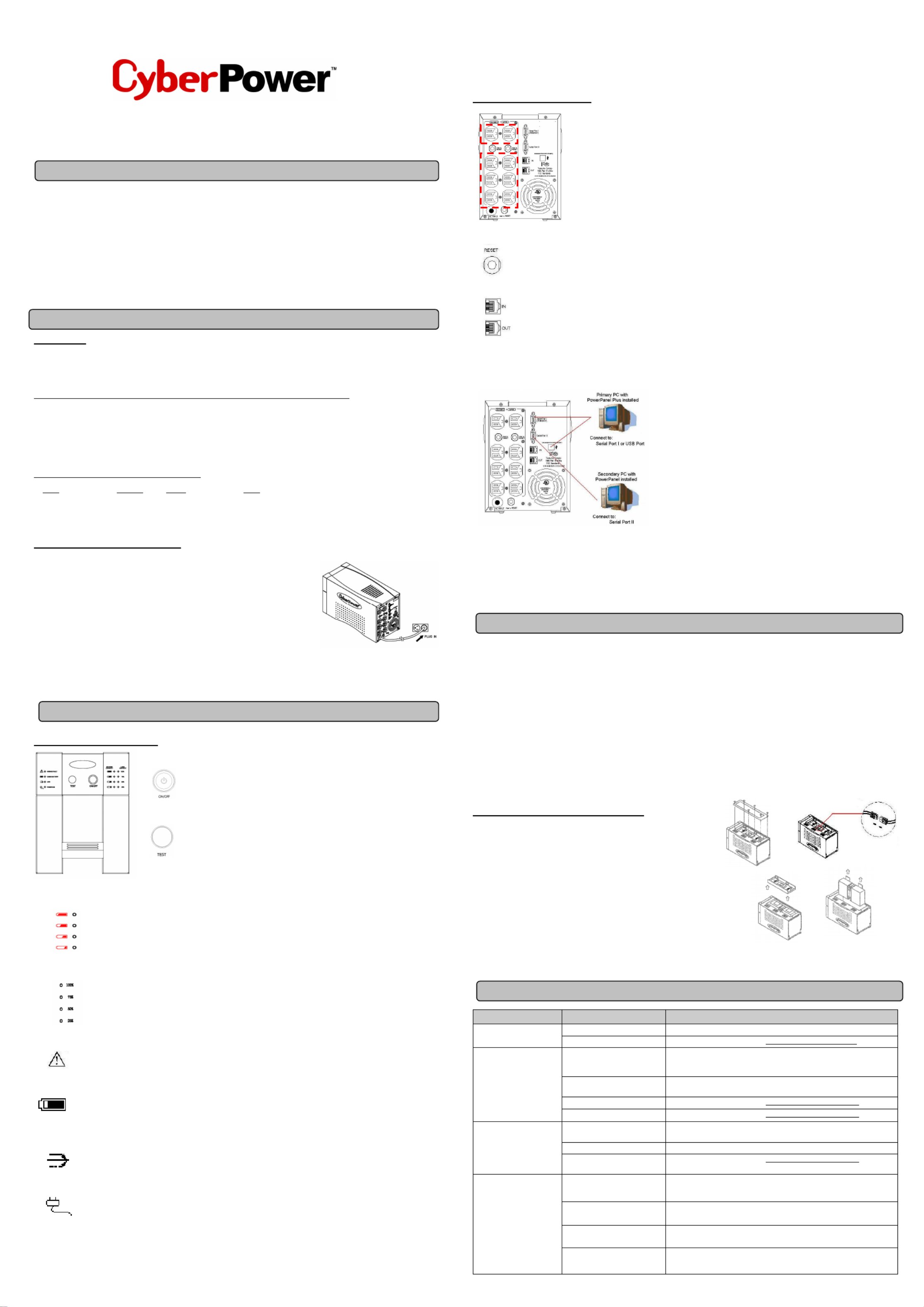
RE PARANCREL DESIPTION
◆◆◆◆ Backup Power for Critical Loads
The U provides 2 battery powered, surge protected outlets for the most critical connected equipments PS
and insuresemporary uninteupted operation of cnected equipments during a poweraure. trron fil
NOTE: When the Us overloaded, the U nteupt wer supply to the other 6 battery PS iPS wi illrrpo
outlets and leave these 2 outlets for critical loads uninterrupted.
◆◆◆◆ Battery Backup and Surge Protection Outlets
This unit provides 6 battery-powered, surge-protected and AVR outlets for connected equipments and
insures uninterrupted operation ocoected eipment during a werailure. f nnqupo f
◆◆◆◆ Circuit Breaker Reset forverload Protection O
Re-settable circuit breakers provi optimal overload protection. de
◆
◆◆
◆ Coication Prottion Ports mmunec
Ethert RJ- Network Protection Ports protecne45t your Phone, Fax and Modem from surges overhe Ethernet/Phone line. t
◆
◆◆
◆ Serial/ USB Ports
The 15/2 provideswo serial and one U ports to aow connection and coication betweenhe UPS and two computers. PP00 PP200 tSBllmmun t
This allows the simultous shutdown of two computer systems. These interfaces are also compatible with the U service provided by anePS
Windows 2000, Wiows NT, Winws XP, Winws Server 20nddodo03.
1. The Primary PC
To control the U and make any change to the eration of the U, PSopPS
plse install the PowerPel in your primary compueaanBusiness Editonter and
then connect itohe Serial Por or U porof the U. t tt ISBt PS
2. The Secondary PC
The secondary computer with PowerPanel installed should be connected to
the serial port . This PC wi shutdown following the user settings in IIll
PowerPanel Software when a wer failure occurs but it is unable to exhibit any po
control over t U. hePS
When powerailure occurs, one of the following shutdown sequences wl be executed: fil
1. If the Primary and Secdary serial ports are both in use: the Primary computer w staro cndown (user contro delay)or shutdown onillt tout lled f
(User Control delay c be set in the PowerPanel Recoendedime is 5 minutes). Once the Primary computer is shutdown, anBusiness Editionmm t
t he U w signal the Secondary computer and initiate the Secondary to shutdown. The U deflt shutdown time is 2 minutes. Therefore, PSillPSau
it is recommended tt Secondary computer is seo shutdown within 1 minute in PowerPanel Software. hat t
2. If only the Secondary serial port is in use: the Secondary computer w shutdown following the user settings in PowerPanel Software. ill
However, the Secry comter w not able to signal the U to stdown. Therefore, the U will only power off when it is in low ondapuillPShuPS
battery.
BATTERY RLACEMENT AND STORAGE EP
Contact your dealer or call the number in this manual for information on battery replacement.
Read and follow the IMPORTANT SAFETY INSTCTIONS RUbefore servicing the battery.Service the battery under t supervision of he
personnel knowledgeable of baeries and their precautionsKett. ep unautrized personnel awayrom baeries. ho ftt
CAUTION! Use only t scified type of battery.See your dealer for replacembatteries. hepeent
CAUTION!The battery may present the risk of electrical shock. Do not dispose of baeries in a fire, as it may explo. Follow all local ttde
ordinances regarding proper disposal of batteries.
CAUTION! Do no or mutilatehe batteries. Relse electrolyte is harmfulot open tea t the skin a eyes and may beoxic. nd t
CAUTION! A baery can present a high risk of short circuit current and electric shock. Take the following precautions before replacing the tt
battery:
1Remove a watcs, ris or other metal objects. . llheng
2Only use tls with insulated handles. . oo
3DO NOTlay tools or otr metal parts on top of battery or any baery terminals. . he tt
4. Wear rubr gloves and ts. beboo
5. Determine if the battery is idvertently groued. If inadvertently grnded, remove source of grnd. nandououCONTACT WITH A GROED UND
BATTERY CAN RULT IN ELECTRICAL SHOCK! ESThe kelihood of such shock wl be reduced if such grounds are removed ring liildu
installation d maintence (applicable to a U and a remote baery supply not having a grounded circuit). ananPStt
BATTERY REPLEMENT PROCEE:ACDUR
1. Turn ofd unplug all ccted equipments. f anonne
2. Turn the U off and plug it fromhe AC power source. PSun t
3Carefully turn the U upside down. Remove the 6 retaining screws and the . PS
cover.
4Disconnect the black a red wires from the baery set. . ndtt
5Remove the battery protection cover and take outhe battery set fromhe . t t
compartment.
6Slide a new battery pack intohe unit. Assemble t baery protection cover, . thett
cable, screws in the reverse sequence oabove steps. f
REMINDER: Rechar t unitor 4 – 8 hours to ensure the U performs gehe fPS
expected runtime
STORAGE:
Firsturn o your U disconnect its power cord fromhe wall outle Disconnecall cables connected to the U to avoid battery drain. To t ffPS and tt.t PS
store your U for an ext period, cover it and store with t battery fully charged. Recharge the baery every three months to insure PSendedhett
battery life. If the battery remains uncharged for an extended period of time, it may suffer permanenloss ocapacity. t f
TROUBLE SHTING OO
Problem Poible Cause Solution ss
The U es t rform PS donope
expected runtime.
Batteries are not fully charged. Recharge t battery by leavinghe U plugged in. he tPS
Battery is slightly worn out. Contact CyberPower Systems ateccyberpowersystems.com. th@
The U will not turn . PSon
The on/ofswitch is designedo f t
prevent damage by rapidly
turning it off and on.
Turnhe U off. tPS
Wai10 seconds andhenurn the U on. t t tPS
The unit is not connected to an
AC outlet.
The unimust be connected to a 1t 10/120v 60Hz outlet.
The battery is worn out. Contact CyberPower Systems atech@cyberpowersystems.com. t
Mechanical problem. Ctact CyberPower Systems atech@cyberpowersystems.com. ont
Outlets do not provide
power to equipment
Circuit breaker is tripped due to
overload
Turn the U off and unplug at least one piece of equipment. Wait 10 PS
seconds, resethe circuit breaker and thenurn the U on. t tPS
Batteries are discharged Allowhe unit to rechargeor at least 4 hours. t f
Unihas been damaged by a t
surge or spike.
ContacCyberPower Systems aech@cyberwersystems.com. t t tpo
PowerPanel Business Edition
is inactive (all icons are gray).
The serial cable is not
connected. Connecthe serial cable to t U unia an op serial port onhe back t hePSt nden t
ofhe computer. You mususe the cable that came with the unit. tt
The serial cable is connected to
the wrong rt. poCheck the back of the computer for an additional serial porMove the t.
cableo this port. t
The unit is not providing battery
power.
Shutdown your computer and turn the U ofPSf. Wait 10 seconds and turn the
U back on. This should resethe unit. PSt
The serial cable is nothe cable t
thawas provided with the unit. t You must use the cable that was included with the unit for the software and
the unito ableo communicate. tbe t
(2)
(1)
(3) (4)
User Manual x1
Please go to www.cyberpowersystems.com for free download PowerPanel Software.
K01-P1K50H0-01
BATTERY
CAPACITY
LOAD
CAPACITY
Product specificaties
| Merk: | CyberPower |
| Categorie: | UPS |
| Model: | Smart App PP2200SW |
| Kleur van het product: | Zwart |
| Gewicht: | 31300 g |
| Snoerlengte: | 2.54 m |
| Vormfactor: | Tower |
| Aantal USB 2.0-poorten: | 1 |
| Certificering: | UL1778, cUL, FCC DOC Class B, RoHS |
| Responstijd: | 4 ms |
| Uitgangsvermogen: | 1500 W |
| Accu/Batterij oplaadtijd: | 8 uur |
| Frequentie: | 50/60 Hz |
| Compatibele besturingssystemen: | Windows 7 |
| Afmetingen (B x D x H): | 177 x 419 x 241 mm |
| Seriële poort(en): | 2 |
| Bedrijfstemperatuur (T-T): | 0 - 35 °C |
| Relatieve vochtigheid in bedrijf (V-V): | 0 - 95 procent |
| Batterijtechnologie: | Sealed Lead Acid (VRLA) |
| Type batterij: | BP9-12 |
| Surge energy rating: | 1796 J |
| Output power capacity: | 2.2 kVA |
| Netspanning, in bedrijf: | 120 V |
| Emergency Power Off (EPO): | Ja |
| Vervangings-batterij cartridge: | BB Battery |
Heb je hulp nodig?
Als je hulp nodig hebt met CyberPower Smart App PP2200SW stel dan hieronder een vraag en andere gebruikers zullen je antwoorden
Handleiding UPS CyberPower

13 Maart 2026
1 Februari 2026
30 Januari 2026
23 December 2025
29 November 2025
29 November 2025
28 November 2025
28 November 2025
28 November 2025
30 September 2025
Handleiding UPS
Nieuwste handleidingen voor UPS
16 Juni 2026
15 Juni 2026
15 Juni 2026
5 Mei 2026
5 Mei 2026
14 April 2026
5 April 2026
5 April 2026
31 Maart 2026
26 Maart 2026