Crydom DRSED Handleiding
Crydom
Niet gecategoriseerd
DRSED
Bekijk gratis de handleiding van Crydom DRSED (2 pagina’s), behorend tot de categorie Niet gecategoriseerd. Deze gids werd als nuttig beoordeeld door 24 mensen en kreeg gemiddeld 4.6 sterren uit 12.5 reviews. Heb je een vraag over Crydom DRSED of wil je andere gebruikers van dit product iets vragen? Stel een vraag
Pagina 1/2

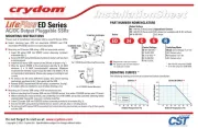
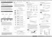
AC/DC Output Pluggable SSRs
ED Serie s
PART NUMBER NOMENCLATURE
Required for valid part number
For options only and not required
for valid part number
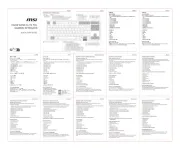
MOUNTING INSTRUCTIONS
Please read all installation instructions before using ED Series SSRs.
Select mounting type. DIN rail mountable (DRSED) and PCB
mountable (PCBSED) sockets are sold separately.
fig. 2 PCBSED Socket Mounting
TO LOCK
ED Series
SSR
fig. 1 DRSED Socket Mounting/Dismounting
TO REMOVE FROM
DIN RAIL
TO INSTALL ON DIN RAIL
TO UNLOCK
ED Series
SSR
Insert ED series SSR into DRSED socket observing terminals’
orientation (fig. 1).
Secure ED SSR using latching mechanism on socket until you hear
a clicking sound.
Install the ED series SSR / socket on the DIN rail as shown in fig.1
Wire the socket DRSED to the input/output side (fig. 5). 24 AWG
minimum, 2 x 14 AWG (stranded/solid) maximum. Maximum
recommended terminal screw torque 5.3-8.85 in lbs (0.60-1.2 N m)
on input/output terminations. Choose wire gauge according to load
current.
To retrieve the ED series SSR from socket, first unlock latching
mechanism, as shown in fig.1, then gently pull the SSR.
Release DRSED socket from DIN rail using a screwdriver. See fig.1.
If multiple units are installed be sure to follow derating curve.
Mounting an ED series SSR using a DIN rail mountable socket:
Before mounting the ED series SSR into the PCBSED socket, first solder PCBSED socket onto PC board.
When soldering the relay terminals, use a soldering iron of 30 to 60W, and quickly complete soldering (within
approximately 3 seconds). Use a non-corrosive resin flux.
Insert ED series SSR into PCBSED socket observing terminals’ orientation (fig. 2).
Secure ED SSR using latching mechanism on socket until you hear a clicking sound.
To retrieve the ED series SSR from socket, first unlock latching mechanism, as shown in fig.2, then gently
pull the SSR.
Mounting an ED series SSR using a PCB mountable socket:
The following deating curves must be observed before installation.
DERATING CURVES
(A)
(B) (C)
6.0
5.0
4.0
3.0
2.0
1.0
10 20 30 40 50 60 70 80
0
Ambient Temperature (ºC)
Load Current (Amps)
ED24xxx
6.0
5.0
4.0
3.0
2.0
1.0
10 20 30 40 50 60 70 80
0
Ambient Temperature (ºC)
Load Current (Amps)
ED10x5 & ED06x5
Series
Operational Current
3: 3 Amps (not available with B & E suffixes)
5: 5 Amps
Output Voltage
06: 1-48 VDC (5 Amps only)
10: 1-80 VDC (5 Amps only)
24: 24-280 VAC
Control Voltage
B: 90-140 VAC *
C: 18-32 VDC
D: 3-15 VDC **
E: 18-36 VAC
F: 48-72 VDC
ED 24 C 5
Switching Mode
Blank: Zero Voltage Turn-On
(AC Output only)
R: Random Turn-On
(AC Output only)
R
* 100-140 VAC range for ED24B5
** 5-15 VDC range for ED06/10D5
3 Amps
5 Amps

WIRING AM DIAGR
(Bottom view)
3
4
2
1
5
3
(14)
5 (A2)
1 (A1)
4
(11)
Load
(Bottom view)
3
(14)
3
4
2
5 (A2)
5
1 (A1)
1
4
(11)
Load
DC/AC
Control voltage
(Top view)
4
2
3
3
(14)
5 (A2)
1 (A1)
4
(11)
Load
(F,G)
(H,J)
(D,E)
fig. 5
fig. 4
fig. 3
(A) UL ratings are for relays only. 00% Duty Cycle.1
(B) Curve based on a minimum spacing between parts of 17mm for ED24x5 and 13mm for
ED24x3. Maximum current @ 0mm spacing is 2.7A for ED24x5 and 2.3A for ED24x3 @ 40ºC.
Derating Value: ED24x5 = 0.135A per mm, ED24x3 = 0.054A per mm.
(C) Curve based on a minimum spacing between parts of 16mm. Maximum current @ 0mm
spacing is 3A. Derating Value: ED06x5, ED10x5 = 0.125A per mm.
(D) DC inductive loads must be diode suppressed.
(E) No grounding required.
(F) For sockets intended for AC input control voltage, the AC line can be wired to either DRS
socket terminal 1 (A1-) or terminal 5 (A2+). Proper polarity must be observed for DC input control
voltage sockets being terminal 5 (A2+) positive with respect to terminal 1 (A1-).
(G) For AC loads, the AC line can be wired to either DRS socket terminal 4 (11) or terminal 3 (14).
The AC load may also be wired on either the line or neutral side of the SSR. For DC loads, the
proper polarity must be observed for the power supply, load and DRS socket with terminal 3 (14)
being positive with respect to terminal 4 (11).
(H) Minimum wire strip lenght 0.197 in (5 mm), maximum 0.256 in (6.5 mm).
(J) Input / Output terminals screw M3 Combo Drive.
SOCKET
Part no.: PCBSED
SOCKET
Part no.: DRSED
RELAY
Part no.: ED series
Rev. 050311
Product specificaties
| Merk: | Crydom |
| Categorie: | Niet gecategoriseerd |
| Model: | DRSED |
Heb je hulp nodig?
Als je hulp nodig hebt met Crydom DRSED stel dan hieronder een vraag en andere gebruikers zullen je antwoorden
Handleiding Niet gecategoriseerd Crydom
24 Mei 2025
Handleiding Niet gecategoriseerd
- Joie
- Konstant Lab
- Dostmann Electronic
- Oromed
- Hacienda
- Ultron
- Gloria
- Lanzar
- Kernau
- Gasmate
- Watts
- TRIUS
- 4ms
- BeeSecure
- Cabere
Nieuwste handleidingen voor Niet gecategoriseerd
7 September 2025
5 September 2025
5 September 2025
5 September 2025
5 September 2025
5 September 2025
4 September 2025
4 September 2025
4 September 2025

4 September 2025