Crestron TSW-760-LB-B Handleiding
Crestron Niet gecategoriseerd TSW-760-LB-B
Bekijk gratis de handleiding van Crestron TSW-760-LB-B (2 pagina’s), behorend tot de categorie Niet gecategoriseerd. Deze gids werd als nuttig beoordeeld door 10 mensen en kreeg gemiddeld 4.3 sterren uit 3 reviews. Heb je een vraag over Crestron TSW-760-LB-B of wil je andere gebruikers van dit product iets vragen? Stel een vraag
Pagina 1/2
TSW-760-LB/TSW-1060-LB
Room Availability Light Bar for TSS-7/TSW-760 & TSS-10/TSW-1060
Installation Guide
Description
The Crestron
®
TSW-760-LB and TSW-1060-LB are room availability light bars for the
Crestron TSS-7/TSW-760 and TSS-10/TSW-1060 touch screens, respectively. When the
light bar is installed onto a touch screen as part of an enterprise room scheduling solution,
the light bar illuminates to indicate the room’s availability.
Additional Resources
Visit the product pages on the Crestron
website (www.crestron.com) for additional
information and the latest rmware
updates. Use a QR reader application on
your mobile device to scan the QR image.
inNET EX logo only needed for inNET
EX products. The mere mention of
inNET EX in a document is not cause to
use the logo.
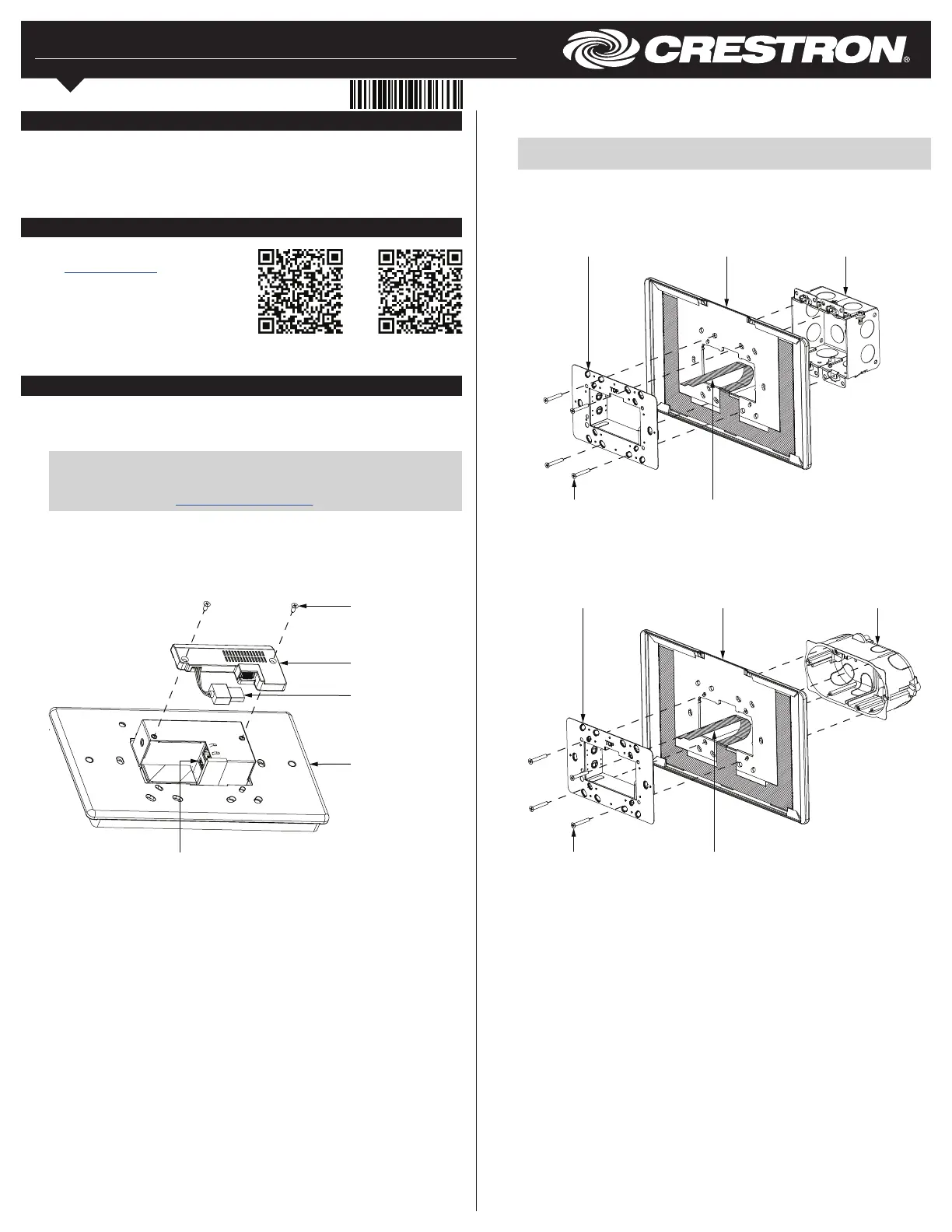
6. Use the removed screws to attach the mounting bracket and light bar to the
electrical box.
NOTE: Pull the ex circuit attached to the light bar through the opening in the
mounting bracket after the light bar and mounting bracket are installed.
Illustrations depicting U.S.-style and European-style installations are shown below.
U.S.-Style Installation
European-Style Installation
Light bar
assembly
Screw (2):
4-40 x 3/8 in
USB connector
Touch screen
USB port
4. Remove the touch screen mounting bracket from the electrical box:
a. For U.S.-style installations, unscrew the four 6-32 x 3/4 in screws.
b. For European-style installations, unscrew the four M3 x 16 mm screws.
c. For U.K.-style installations, unscrew the two M3 x 25 mm screws.
5. Align the light bar with the electrical box.
Installation
To install the TSW-760-LB and TSW-1060-LB light bars:
1. If the light bar is being added to an existing touch screen installation, pull the touch
screen carefully out its mounting bracket and disconnect the Ethernet cable.
NOTE: If the touch screen is secured to the mounting bracket with a security
latch, refer to the removal procedure described in the
TSW-560/TSW-760/TSW-1060 DO Guide (Doc. 7926) or the TSS-7/TSS-10
DO Guide (Doc. 8326) at www.crestron.com/manuals.
2. Use the two included 4-40 x 3/8 in screws to attach the light bar assembly to the
rear of the touch screen.
3. Insert the assembly’s USB connector into the USB port on the rear of the touch
screen.
TSW-760-LBTSW-1060-LB
Touch screen
mounting bracket
Light bar
2-gang
U.S. electrical box
Flex circuitScrew (4): 6-32 x 3/8 in
Touch screen
mounting bracket
Light bar
2-gang European
electrical box
Flex circuitScrew (4): M3 x 16 mm
Product specificaties
| Merk: | Crestron |
| Categorie: | Niet gecategoriseerd |
| Model: | TSW-760-LB-B |
Heb je hulp nodig?
Als je hulp nodig hebt met Crestron TSW-760-LB-B stel dan hieronder een vraag en andere gebruikers zullen je antwoorden
Handleiding Niet gecategoriseerd Crestron

26 Mei 2026
7 Maart 2026
4 Maart 2026
28 Januari 2026
27 Januari 2026
4 December 2025
3 December 2025
2 December 2025
2 December 2025
2 December 2025
Handleiding Niet gecategoriseerd
Nieuwste handleidingen voor Niet gecategoriseerd
23 Juli 2026
23 Juli 2026
23 Juli 2026
23 Juli 2026
23 Juli 2026
23 Juli 2026
23 Juli 2026
23 Juli 2026
23 Juli 2026
22 Juli 2026