Crestron SSW-102 Handleiding


Lees hieronder de 📖 handleiding in het Nederlandse voor Crestron SSW-102 (2 pagina's) in de categorie Niet gecategoriseerd. Deze handleiding was nuttig voor 18 personen en werd door 2 gebruikers gemiddeld met 4.5 sterren beoordeeld

Pagina 1/2
DO GUIDE
The brightness of the SSW may be custom programmed as follows:
• If the SSW is connected to a touch screen, brightness is controlled by sending a custom
property to the touch screen in Crestron Fusion® software. For more information, refer to
the embedded Crestron Fusion help le.
• If the SSW is connected to a control system, brightness is controlled via custom
programming in SIMPL Windows or Crestron Studio. For more information, refer to the
embedded SIMPL Windows or Crestron Studio help les.
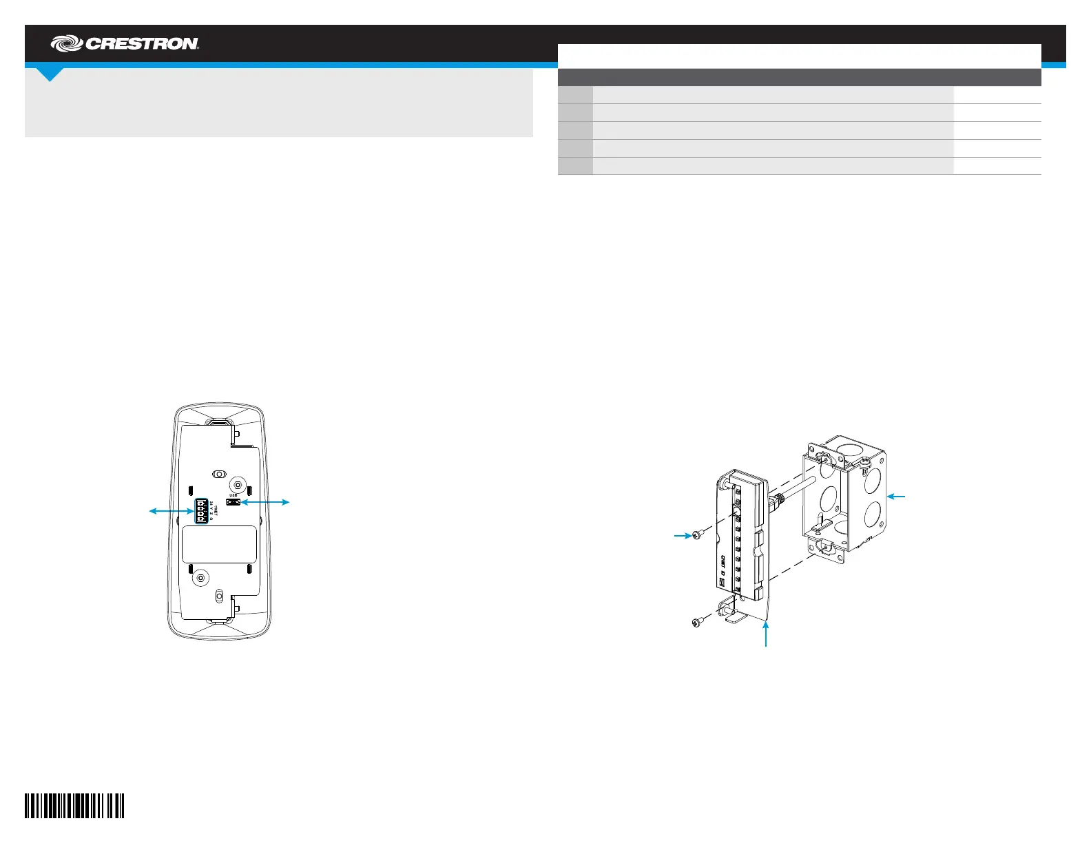
DO Install the Device
The SSW installs over a standard 1-gang U.S. electrical box. Once installed, the touch screen
protrudes 8.43 in (214 mm) from the mounting surface.
To install the SSW:
1. Once all cable connections have been made, attach the device assembly to the electrical
box using the two included 6-32 x 5/16 in screws and a Phillips screwdriver.
NOTE: For retrot installations, the SSW may be installed over a 1-gang plaster ring using
the same installation method described above.
SSW Series
Room Availability Hallway Sign, Wall Mount
DO Connect the Device
The Crestron® SSW room availability hallway sign may be powered and controlled by a Crestron
TSS-7, TSS-10, TSW-760 or TSW-1060 touch screen via USB, or by a Crestron control system or
DMPS3 device via a Cresnet® network connection. Both connection methods are described below.
NOTE: All cable connections must be made prior to installing the SSW.
• Use the included USB cable to connect the SSW to the touch screen. Connect USB:
the cable’s USB A connector to the touch screen and the micro USB connector to the
SSW assembly. Out-of-the-box functionality is established via the touch screen room
scheduling application, with no programming required.
NOTE: The TSS-7 and TSW-760 may use either PoE (Power over Ethernet) or PoE+ to
supply power to the SSW over USB , but the TSS-10 and TSW-1060 must use only PoE+ to
supply power to the SSW.
• Use any standard Cresnet cable and the included 4-pin terminal block to Cresnet:
connect the SSW to a Crestron control system or DMPS3 device. The SSW is powered and
controlled over Cresnet via programming in SIMPL Windows or Crestron Studio® software.
NOTE: The button on the front of the assembly is used to identify the device on the CNET ID
network using the Network Device Tree View in Crestron Toolboxâ„¢ software. For more information,
refer to the embedded Crestron Toolbox help le.
DO Check the Box
QTY ITEM PART NUM.
1 Bezel, Wall Sign 4525866
1 Cable, USB 2.0, A - micro B, 6 ft (1.83 m) 2038114
1 Connector, 4-Pin 2003576
2 Screw, 4-40 x 1/2 in, SEMS, Pan Head, Phillips 2011592
2 Screw, 6-32 x 5/16 in, Pan Head, Phillips 2007221
CNET (24 Y Z G):
To Cresnet®
network device
USB (Micro):
To touch screen
Assembly
1-gang U.S.
electrical
box
Screws (2):
6-32 x 5/16 in
DO GUIDE
5. Remove the plastic lm from the acrylic face once it is secured.
6. Slide the included bezel carefully over the acrylic face until the magnets on the bezel snap
into place against the assembly.
DOC. 7969G (2048129) 07.18
Specications subject to change wit hout notice.
2. Align the two mounting holes on the acrylic face (included with the SSW kit or purchased
separately) with the mounting posts on the assembly.
3. Attach the acrylic face to the assembly so that the posts on the assembly engage the holes
on the acrylic face. The acrylic face stays in place after it is attached to the assembly.
4. Using a Phillips screwdriver, secure the acrylic face to the assembly with the two included
4-40 x 1/2 in screws.
The illustration below depicts the procedure for attaching an SSW-ACR series acrylic face
face to the assembly. The same attachment procedure applies to other acrylic faces that
are compatible with the SSW.
This product is Listed to applicable UL
® Standards and requirements tested by Underwriters Laboratories Inc.
Ce produit est homologué selon les normes et les exigences UL applicables par Underwriters Laboratories Inc.
Federal Communications Commission (FCC) Compliance Statement
This device complies with part 15 of the FCC Rules. Operation is subject to the following two conditions:
(1) This device may not cause harmful interference, and (2) this device must accept any interference received, including interference
that may cause undesired operation.
CAUTION: Changes or modications not expressly approved by the manufacturer responsible for compliance could void the user’s
authority to operate the equipment.
NOTE: This equipment has been tested and found to comply with the limits for a Class B digital device, pursuant to part 15 of the
FCC Rules. These limits are designed to provide reasonable protection against harmful interference in a residential installation.
This equipment generates, uses and can radiate radio frequency energy and, if not installed and used in accordance with the
instructions, may cause harmful interference to radio communications. However, there is no guarantee that interference will not
occur in a particular installation.
If this equipment does cause harmful interference to radio or television reception, which can be determined by turning the
equipment off and on, the user is encouraged to try to correct the interference by one or more of the following measures:
• Reorient or relocate the receiving antenna.
• Increase the separation between the equipment and receiver.
• Connect the equipment into an outlet on a circuit different from that to which the receiver is connected.
• Consult the dealer or an experienced radio/T V technician for help.
Industry Canada (IC) Compliance Statement
CAN ICES-3(B)/NMB-3(B)
The specic patent s that cover C restron product s are listed at .www.crestron.com/legal/patents
The product warranty can be f ound at .www.crestron.com/legal/sales-terms-conditions-warranties
Cert ain Crest ron products contain open source sof t ware. For s pecic inf ormation, please visit ww w.crestron.com/legal /open-source-soft ware.
Crestron, t he Crestr on logo, Cresnet , Crestron Fus ion, C restron Stu dio, and Crestr on Toolbox are eit her t rademarks or register ed trademarks of Crestron Electr onics, Inc. in the United States
and/or ot her count ries. UL and the UL logo are eit her trademarks or registered tr ademarks of Underwriters Laboratories, Inc., in the Un ited States and/or o ther coun tries. Ot her tr ademarks,
registered trademarks , and trade names may be used in this document to refer to either the entities claiming th e marks and names or t heir products. Cres tron disclaims any propriet ary interest
in the marks and names of others. Crest ron is n ot responsible for errors in t ypography or photography.
This document was writt en by the Technical Publications department at Crest ron.
©2018 Crestron Electronics, Inc.
DO Learn More
Visit the website for additional information and the latest rmware updates. To learn
more about this product, use a QR reader application on your mobile device to scan
the QR image.
Crestron Electronics
15 Volvo Drive, Rockleigh, NJ 07647
888.CRESTRON | www.crestron.com
Screws (2):
4-40 x 1/2 in
SEMS
Acrylic
face
Assembly


Product specificaties

Merk: Crestron
Categorie: Niet gecategoriseerd
Model: SSW-102

Heb je hulp nodig?

Als je hulp nodig hebt met Crestron SSW-102 stel dan hieronder een vraag en andere gebruikers zullen je antwoorden


Handleiding Niet gecategoriseerd Crestron

Handleiding Niet gecategoriseerd

Nieuwste handleidingen voor Niet gecategoriseerd