Crestron CLX-PWS75 Handleiding
Crestron
Niet gecategoriseerd
CLX-PWS75
Bekijk gratis de handleiding van Crestron CLX-PWS75 (6 pagina’s), behorend tot de categorie Niet gecategoriseerd. Deze gids werd als nuttig beoordeeld door 33 mensen en kreeg gemiddeld 3.7 sterren uit 17 reviews. Heb je een vraag over Crestron CLX-PWS75 of wil je andere gebruikers van dit product iets vragen? Stel een vraag
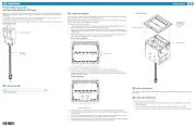
Pagina 1/6

CLT- & CLX-PWS75
Functional Summary
NOTE: Modules and terminal blocks must be installed
into the lowest available spaces and continue toward the
top of the enclosure.
The Crestron
®
75 Watt Power Supply Terminal Block and
Module (CLT-PWS75 and CLX-PWS75, respectively)
are considered a single entity and must be used together.
They ship separately to permit termination of the field
wiring to the CLT-PWS75 prior to installation of the
CLX-PWS75, as described in this guide. The
CLX-PWS75 is a power supply module that provides up
to 75 Watts of Cresnet
®
power to Crestron equipment.
The terminal block and module can be mounted in any
Crestron Automation Enclosure (CAEN-Series
Enclosures, refer to the NOTE in the next column). The
terminal block is designed to terminate the circuit feed
(LINE and NEUTRAL) and distribute the power to a
connector on a supplied cable assembly (LOAD) that
connects to the power supply module. The power supply
module operates with an input of 100 to 250 VAC, 2.3A
(maximum). The power supply module has a fuse that
protects the 24 VDC output. If the network power lines
are shorted, the fuse is blown. As a result, the NET
POWER LED extinguishes.
Terminal Block & Module Locations (Single-wide Enclosure)
GROUNDING
TERMINAL
BLOCK
MODULETERMINAL
BLOCK
Regulatory Compliance
This product is Listed to applicable UL Standards
and requirements by Underwriters Laboratories Inc.
Terminal Block & Module Locations (Double-wide Enclosure)
MODULE
TERMINAL BLOCK
(RIGHT)
GROUNDING TERMINAL BLOCKS
TERMINAL BLOCK
(LEFT)
MODULE
Installation
The terminal block and module must be mounted into a
Crestron Automation Enclosure by a licensed electrician,
in accordance with all national and local codes.
CAUTION: This equipment is for indoor use only and
needs to be air-cooled. Mount in a well-ventilated area.
The ambient temperature must be 32°F to 104°F (0°C to
40°C). The relative humidity must be 0% to 90% (non-
condensing).
Crestron Electronics, Inc. Installation Guide – DOC. 6348B
15 Volvo Drive Rockleigh, NJ 07647 (2012603)
Tel: 888.CRESTRON 11.11
Fax: 201.767.7576 Specifications subject to
www.crestron.com change without notice.
Terminal blocks are installed along the left side of single-
wide enclosures and along the outside edges (left and
right sides) of double-wide enclosures. Modules are
installed along the right side of single-wide enclosures
and side-by-side in the center of double-wide enclosures.
When installing modules and terminal blocks in a double-
wide enclosure, be sure to invert units on the right side so
that they can be properly wired. Refer to the illustrations
shown in the next column when considering the location
of terminal blocks and modules within an enclosure.

Terminal Block & Module Crestron CLT- & CLX-PWS75
Terminal Block Installation and
Field Wiring
Wiring Diagram of the Terminal Block to the Feed and
Load(s)(Single-wide and Left Side Double-wide Enclosures)
AREA FOR MODULE
LOCATION LABEL
TERMINAL
BLOCK
WIRING LABEL
GROUND
NEUTRAL
LINE
FROM 15 OR 20 AMP
CIRCUIT BREAKER
TO BLACK LEAD OF
CABLE ASSEMBLY
TO WHITE LEAD OF
CABLE ASSEMBLY
TO GREEN LEAD OF
CABLE ASSEMBLY
CAUTION: RISK OF ELECTRIC SHOCK—MORE
THAN ONE DISCONNECT SWITCH MAY BE
REQUIRED TO DE-ENERGIZE THE EQUIPMENT
BEFORE SERVICING.
NOTE: Both left-side and right-side adhesive wiring
labels are provided. The left-side labels are used in both
single and double-wide enclosures. The right-side labels
are only used in double-wide enclosures.
1. Remove the backing from the left or right
adhesive wiring label.
2. Apply the adhesive label by aligning the holes in
the label with the holes on the Crestron
Automation Enclosure where the terminal block
is to be mounted. The wiring label lies beneath
the terminal block as shown in the two wiring
diagrams on this page.
Wiring Diagram of the Terminal Block to the Feed and
Load(s)(Right Side Double-wide Enclosures)
TERMINAL
BLOCK
WIRING LABEL
LINE
FROM 15 OR 20 AM
P
CIRCUIT BREAKER
NEUTRAL
GROUND
AREA FOR MODULE
LOCATION LABEL
TO GREEN LEAD OF
CABLE ASSEMBLY
TO BLACK LEAD OF
CABLE ASSEMBLY
TO WHITE LEAD OF
CABLE ASSEMBLY
3. Use the two supplied self-tapping pan Phillips
screws (8B x 1/4 length) to secure the terminal
block to the Crestron Automation Enclosure.
NOTE: Use copper conductors only – rated
75°C.
4. With the circuit breaker turned off, connect the
circuit feeds (LINE, NEUTRAL, and GROUND)
to the terminal block per the markings provided
on the wiring label (as shown in the following
diagram). Terminal blocks accept one 14 - 10
AWG wire. Wires should be stripped to 1/2 inch.
Tighten terminal blocks to 9 in-lbs.
NOTE: LINE and NEUTRAL lines can be
jumped to other terminal blocks in the
enclosure.
5. Grounding terminal blocks are available in the
cabinet for termination of ground wires. Tighten
to 35 in-lbs. (14 – 10 AWG).
Module Installation
CAUTION: The module contains electrostatic sensitive
devices (ESDs); unit must be handled from metal chassis
– do not touch PC board or components.
6. Connect each wire from the connector assembly
to the terminal block. Each wire is the same
color as the terminal to which it should be
connected. Wires are pre-stripped to 1/2 inch.
Tighten to 9 in-lbs.
NOTE: Modules are to be installed after enclosure has
been completely wired. Refer to the terminal block
installation procedure on the top of the page for details.
7. Test the circuit for electrical faults by turning on
the circuit breaker and checking that the breaker
does not trip and that power is supplied to the
connector of the cable assembly.
1. Use the four supplied self-tapping screws (8B x
1/4 length) to secure the module to the enclosure.
2. If the module is being installed below another
module within the enclosure, attach the supplied
module interconnect cable between the two
2 •
•
•
•• Terminal Block & Module: CLT- & CLX-PWS75 Installation Guide – DOC. 6348B

Crestron CLT- & CLX-PWS75 Terminal Block & Module
modules. The following illustration depicts the
area within a double-wide enclosure where the
corners of four modules meet.
NOTE: Do not power up system until all wiring is
verified. Care should be taken to ensure data (Y, Z) and
ground (G) connections are not crossed when connecting
Cresnet devices.
NOTE: One wire on the module interconnect
cable may be a different color from the rest. The
color has no bearing on its orientation during
installation.
When calculating the length of wire for a particular
Cresnet run, the wire gauge and the Cresnet power usage
of each network unit to be connected must be taken into
consideration. Use Crestron Certified Wire only. If
Cresnet units are to be daisy-chained on the run, the
Cresnet power usage of each network unit to be daisy-
chained must be added together to determine the Cresnet
power usage of the entire chain. If the unit is home-run
from a Crestron system power supply network port, the
Cresnet power usage of that unit is the Cresnet power
usage of the entire run. The wire gauge and the Cresnet
power usage of the run should be used in the following
equation to calculate the cable length value on the
equation’s left side.
Use Module Interconnect Cable to Wire Module to Module
MODULE
INTERCONNECT
CABLE ATTACHED
CONNECTION
NOT
MADE
Cable Length Equation
3. Connect the module’s female connector to the
male connector that is wired to the terminal
block.
Where:
R = 6 Ohms (Crestron Certified Wire: 18 AWG (0.75 MM
2
))
or 1.6 Ohms (Cresnet HP: 12 AWG (4MM
2
))
L = Length of run (or chain) in feet.
P = Cresnet power usage of entire run (or chain).
L <
R x P
40,000
4. Turn on the circuit breaker and verify that the
breaker does not trip.
NOTE: If the fuse is to be replaced, replace
only with the same fuse type and rating. A time
lag is required.
Make sure the cable length value is less than the value
calculated on the right side of the equation. For example,
a Cresnet run using 18 AWG Crestron Certified Wire and
drawing 20 watts should not have a length of run more
than 333 feet. If Cresnet HP is used for the same run, its
length could extend to 1250 feet (381 meters).
Network Device Wiring
CAUTION: In order to ensure optimum performance
over the full range of your installation topology, Crestron
Certified Wire and only Crestron Certified Wire may be
used. Failure to do so may incur additional charges if
support is required to identify performance deciencies
because of using improper wire.
NOTE: All Crestron certified Cresnet wiring must
consist of two twisted pairs. One twisted pair is the +24V
conductor and the GND conductor and the other twisted
pair is the Y conductor and the Z conductor.
NOTE: When daisy-chaining Cresnet units, strip the
ends of the wires carefully to avoid nicking the
conductors. Twist together the ends of the wires that share
a pin on the network connector and tin the twisted
connection. Apply solder only to the ends of the twisted
wires. Avoid tinning too far up the wires or the end
becomes brittle. Insert the tinned connection into the
Cresnet connector and tighten the retaining screw. Repeat
the procedure for the other three conductors.
CAUTION: Use only Crestron power supplies for
Crestron equipment. Failure to do so could cause
equipment damage or void the Crestron warranty.
CAUTION: Provide sufficient power to the system.
Insufficient power can lead to unpredictable results or
damage to the equipment. Please use the Crestron Power
Calculator (www.crestron.com/calculators
) to help
calculate how much power is needed for the system.
NOTE: For larger networks (i.e., greater than 28 network
devices), it may become necessary to add a Cresnet
Hub/Repeater (CNXHUB) to maintain signal quality
throughout the network. Also, for networks with lengthy
cable runs it may be necessary to add a Hub/Repeater
after only 20 devices.
CAUTION: Possible equipment damage if miswired.
NOTE: When installing network wiring, refer to the
latest revision of the wiring diagram(s) appropriate to
your specific system configuration, available from the
Crestron Web site.
Installation Guide – DOC. 6348B Terminal Block & Module: CLT- & CLX-PWS75 •
•
•
•• 3
Product specificaties
| Merk: | Crestron |
| Categorie: | Niet gecategoriseerd |
| Model: | CLX-PWS75 |
Heb je hulp nodig?
Als je hulp nodig hebt met Crestron CLX-PWS75 stel dan hieronder een vraag en andere gebruikers zullen je antwoorden
Handleiding Niet gecategoriseerd Crestron

9 September 2025
9 September 2025
9 September 2025
9 September 2025
9 September 2025
9 September 2025
9 September 2025
8 September 2025
8 September 2025
8 September 2025
Handleiding Niet gecategoriseerd
Nieuwste handleidingen voor Niet gecategoriseerd
16 September 2025

16 September 2025
16 September 2025

16 September 2025
16 September 2025

16 September 2025
16 September 2025
16 September 2025

16 September 2025
16 September 2025