Crestron CAEN-5X2-MLO-120/2P Handleiding

Crestron Niet gecategoriseerd CAEN-5X2-MLO-120/2P

Bekijk gratis de handleiding van Crestron CAEN-5X2-MLO-120/2P (8 pagina’s), behorend tot de categorie Niet gecategoriseerd. Deze gids werd als nuttig beoordeeld door 3 mensen en kreeg gemiddeld 4.5 sterren uit 2 reviews. Heb je een vraag over Crestron CAEN-5X2-MLO-120/2P of wil je andere gebruikers van dit product iets vragen? Stel een vraag

Pagina 1/8
CAEN- MLO
In troduction
Crestron
®
- CAEN MLO Series automation enclosures provide a professional centralized dimming solution for residential and
commercial applications. CAEN MLO enclosures are available in three sizes for surface and flush wall- and allow -mount
installation. They provide a manageable installation with abundant provisions for wire termination and electrical knockouts.
Features and Functions
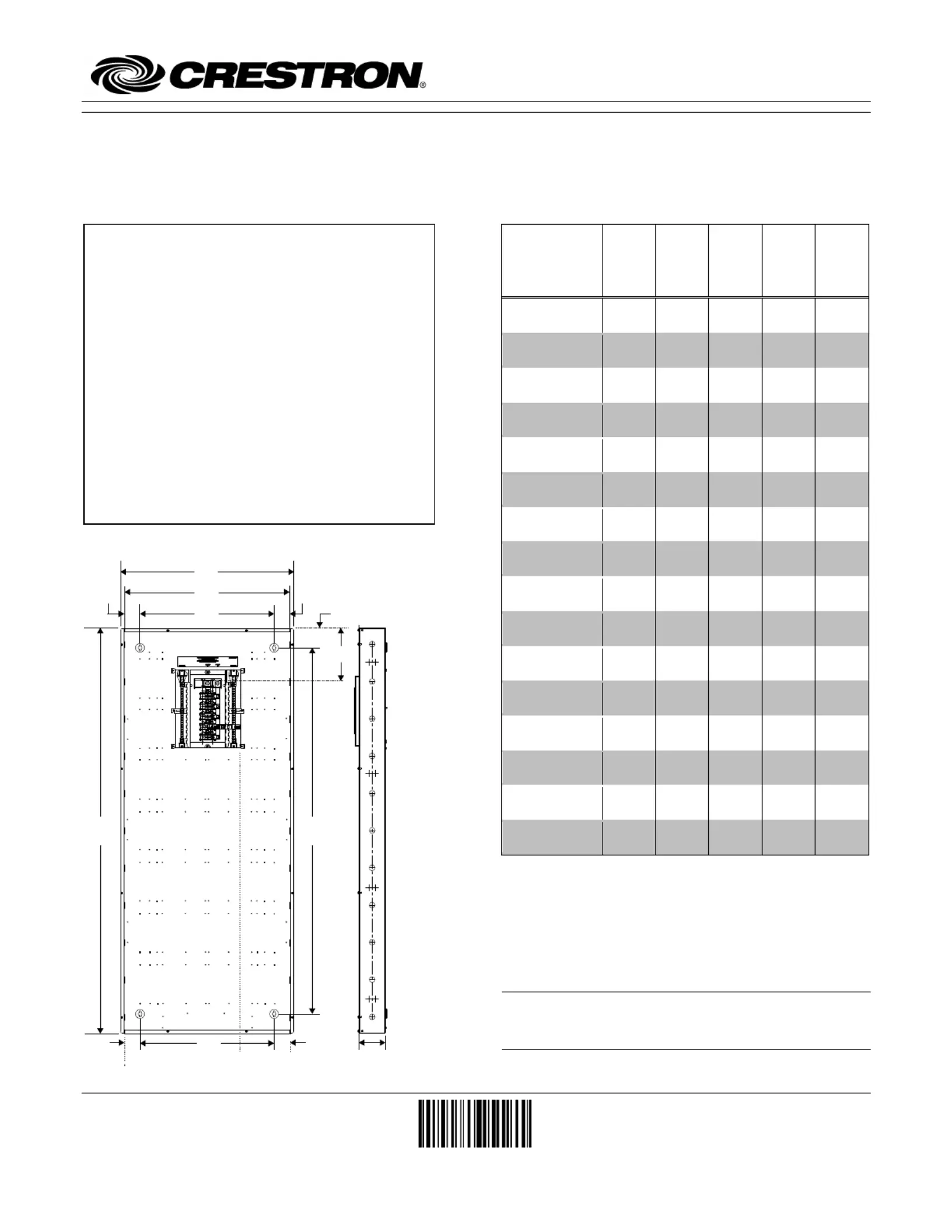
Specifications
DIMENSIONS
1
CAEN-
5x2-
MLO-
120/2P
CAEN-
5x2-
MLO-
120/3P
CAEN-
5x1-
MLO-
120/2P
CAEN-
5x1-
MLO-
120/3P
CAEN-
3x1-
MLO-
120/2P
H1
62
(1575)
62
(1575)
62
(1575)
62
(1575)
38 7/8
( )987
H2
2 11/16
(68)
2 11/16
(68)
2 11/16
(68)
2 11/16
( )68
2 1/8
(53)
H3
56
(1422)
56
(1422)
56
(1422)
56
(1422)
34
( )863
H4
7 5/8
(194)
7 5/8
(194)
7 5/8
(194)
7 5/8
(194)
6
(153)
W1
2 6 1/2
(673)
2 6 1/2
(673)
15 3/8
( )390
15 3/8
( )390
15 3/8
( )390
W2
25 1/2
(647)
25 1/2
(647)
14 3/8
(365)
14 3/8
(365)
14 3/8
(365)
W3
2 1/2
(63)
2 1/2
(63)
1 3/4
(44)
1 3/4
(44)
1 3/4
(44)
W4
20 1/2
(520)
20 1/2
(520)
10 7/8
(276)
10 7/8
(276)
10 7/8
(276)
W5
2
20 1/2
(520)
20 1/2
(520)
9 7/8
(250)
9 7/8
(250)
9 7/8
(250)
W6
2 1/2
(63)
2 1/2
(63)
2 3/4
(69)
2 3/4
(69)
2 3/4
(69)
D1
4 1/8
(104)
4 1/8
(104)
4 1/8
(104)
4 1/8
(104)
4 1/8
(104)
Cover
Thickness
3
1/16
(1)
1/16
(1)
1/16
(1)
1/16
(1)
1/16
(1)
Cover Height
62 3/4
(1593)
62 3/4
(1593)
62 3/4
(1593)
62 3/4
(1593)
39 5/8
(1006)
Cover Width
27 1/4
(692)
27 1/4
(692)
16 1/8
(409)
16 1/8
(409)
16 1/8
(409)
Weight (empty)
4
73
(33.2)
73
(33.2)
50
(22.7)
50
(22.7)
33
(15)
Maximum
Weight (filled)
141
(64)
141
(64)
88
(40)
88
(40)
53
(24.1)
1. Length is specified in inches and millimeters (in parentheses).
Weight is specified in pounds and kilograms (in parentheses).
2. The lower keyholes are not symmetrically spaced within
single- wide enclosures.
3. Thickness does not include breaker access door. The breaker
access door extends 11/16 inches (18 millimeters) above the cover
on all cabinets.
4. Weight (empty) is the weight of an empty enclosure with cover.
NOTE: Double-winged mounting holes are located on
the enclosure, which allow inverted mounting in flood
prone areas without violating breaker height standards.
W1
W2
W4
W3
W5
H1
H2
H3
H4
W6
D1
W3
W6
Houses Crestron lighting modules, terminal blocks,
automation control system, circuit breaker panel, up
to 80 controlled circuits, up to 20 circuit breakers,
dead front, and third party products-
Split phase (120/240 Vac) or three phase
(120/208 Vac) main lugs at 50/60 Hz phase- -to
neutral and 225 A max
16-gauge galvanized steel box, invertible
Flush or surface mount installation
Vented front cover with hinged breaker access door
Eaton
®
CH circuit breakers (20 A, single- pole,
120 V, 10 kAIC, and 4 AWG max wire gauge):
CLB- -120 20A, CLB-120 20A- - AFCI, and
CLB- - -120 20A GFCI (all sold separately)
Crestron Electronics, Inc. Installation Guide DOC. 7579C
15 Volvo Drive Rockleigh, NJ 07647 (2037330)
Tel: 888.CRESTRON 06.14
Fax: 201.767.7576 Specifications subject to
www.crestron.com change without notice.
Automation Enclosures with Integrated Breaker Panel Crestron CAEN-MLO
Regulatory Compliance Conformité Reglementaire
This product is Listed to applicable UL Standards Ce produit est homologué selon les normes et les
and requirements by Underwriters Laboratories Inc. exigences UL applicables par Underwriters
Laboratories Inc.
As of the date of manufacture, the CAEN- MLO Series has been tested and found to comply with
specifications for CE marking.
Federal Communications Commission (FCC) Compliance Statement
These devices comply with part 15 of the FCC Rules. Operation is subject to the following conditions:
(1) These devices may not cause harmful interference and (2) these devices must accept any interference
received, including interference that may cause undesired operation.
CAUTION: Changes or modifications not expressly approved by the manufacturer responsible for
compliance could void the users authority to operate the equipment.
NOTE: This equipment has been tested and found to comply with the limits for a Class B digital device,
pursuant to part 15 of the FCC Rules. These limits are designed to provide reasonable protection against
harmful interference in a residential installation. This equipment generates, uses and can radiate radio
frequency energy and, if not installed and used in accordance with the instructions, may cause harmful
interference to radio communications. However, there is no guarantee that interference will not occur in a
particular installation. If this equipment does cause harmful interference to radio or television reception,
which can be determined by turning the equipment off and on, the user is encouraged to try to correct the
interference by one or more of the following measures:
Reorient or relocate the receiving antenna
Increase the separation between the equipment and receiver
Connect the equipment into an outlet on a circuit different from that to which the receiver is connected
Consult the dealer or an experienced radio/TV technician for help
Industry Canada (IC) Compliance Statement Industrie Canada (IC) Déclaration de conformité
CAN ICES-3(B)/NMB 3(B)-
2
Automation Enclosures with Integrated Breaker Panel: CAEN-MLO Installation Guide DOC. 7579C
Crestron CAEN-MLO Automation Enclosures with Integrated Breaker Panel
Installation
The enclosure must be mounted by a licensed electrician
in accordance with all national and local codes. Refer to
the table on the first page for the weight of a fully loaded
enclosure.
When choosing components to place in the enclosure,
refer to the Specifications table to ensure that the
maximum weight capacity is not exceeded. Each
modules product page on the Crestron website lists the
modules weight.
CLT terminal blocks must be mounted using the screw
holes shown in the Mounting Details diagrams on
page 4.
CAUTION: These enclosures house equipment that
needs to be air cooled. Therefore, mount in a well- -
ventilated area. The ambient temperature range should be
32°F to 104 C to 40°F (0° °C). The relative humidity
should range from 10% to 90% (non-condensing).
Furthermore, allow adequate clearance in front of the
vented cover for servicing and ventilation.
CAUTION: When installing modules in the enclosure,
start at the bottommost module space. If the top module
space (or top two module spaces for a double-wide) is
filled, each feed into the top module must be derated by
25% so that each feed carries no more than 12 A.
NOTE: Enclosures are intended for indoor use only.
NOTE: When flush mounting, 5/8 in (16 mm) drywall is
preferred.
Wiring
CAUTION: All power feeds must be protected by a 15
or 20 A ground fault, arc fault, or thermal magnetic circuit
breakers (sold separately).
NOTE: Use copper conductors only rated 75°C.
NOTE: All wiring must be installed in accordance with
all national and local electrical codes.
NOTE: Six snap bushings are supplied. If required,
insert into knockouts at the bottom and top of the
enclosure to prevent damage to low voltage wiring.
Class 1 and Class 2 field wires must be kept separate.
Refer to the illustrations on pages 4 and 5 -showing single
wide and double-wide wiring details. Areas for high
voltage (Class 1) wiring are along the top and side(s) of
the unit. The lower area is for low voltage (Class 2)
wiring.
Tighten all CLT terminal block screws and grounding
terminal block screws to the torque specified in the Wire
Gauge and Torque Data table in the next column.
CAUTION: Failure to properly tighten the screws may
result in poor electrical connection and overheating of the
terminals.
To wire - the CAEN MLO, insert breakers using the
following procedure:
1. Align the neutral clip with the breaker slot.
2. Press firmly down on the back of the breaker to
clip the breaker onto the neutral bar
.
3. R
ock the breaker forward and press firmly on the
front of the breaker to attach the panel.
Wire Gauge and Torque Data
WIRE GAUGE
(AWG)
TORQUE
(in lb)
CLT Terminal
Blocks
22 10 9
Grounding
Terminal Blocks
14 10 35
8 40
64 45
Main Lugs
5x1/5x2:
4/0 (max)
225
3x1:
2/0 (max)
225
Neutral Lug
(Slotted Screw)
4 2/0 50
Breakers
14 2010
8 25
64 35
Key Typical Items - in a CAEN MLO Enclosure
CLX-Series
Module
CLT-Series
Terminal Blocks
Professional Automation
Computers
PA PAC2 ) (L and C2M (R)
Dead Front
Breakers
Panel
Grounding Terminal Blocks
Installation Guide DOC. 7579C Automation Enclosures with Integrated Breaker Panel: CAEN- 3MLO


Product specificaties

Merk: Crestron
Categorie: Niet gecategoriseerd
Model: CAEN-5X2-MLO-120/2P

Heb je hulp nodig?

Als je hulp nodig hebt met Crestron CAEN-5X2-MLO-120/2P stel dan hieronder een vraag en andere gebruikers zullen je antwoorden