Bosch Pilot Ignition 10P Handleiding
Bosch
Niet gecategoriseerd
Pilot Ignition 10P
Bekijk gratis de handleiding van Bosch Pilot Ignition 10P (11 pagina’s), behorend tot de categorie Niet gecategoriseerd. Deze gids werd als nuttig beoordeeld door 261 mensen en kreeg gemiddeld 4.1 sterren uit 131 reviews. Heb je een vraag over Bosch Pilot Ignition 10P of wil je andere gebruikers van dit product iets vragen? Stel een vraag
Pagina 1/11

1 Main Cover 5 Cold Water Inlet
2 Inspection Window 6 Hot Water Supply
3 Access Panel 7 Mounting Point
4 Gas Inlet 8 Horizontal Flue
A-D Dimensions on page 2 Fig 3
Fig. 1
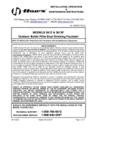
This appliance must be installed in accordance with the manufacturer’s installation instructions,
AG 601, NZ 5261, AS/NZS 3500.4.2 and all Local Water, Building and Gas fitting regulations
To be installed and serviced only by an authorised person
This appliance is not suitable for use as a pool heater
The “authorised installing person” is responsible for :
1. Correct commissioning of this appliance.
2. Ensure unit performs to the specifications stated on the rating label.
3.. Demonstrate operation of unit to customer before leaving.
4. Hand these instructions to customer.
Failure to install this appliance in accordance with these installation instructions may
void warranty
In the interest of continued product improvement, Bosch reserves ther right to alter the specifications
without notice.
25/10/2011

Installation
Install only on an external wall, as close as possible to the most frequently used hot
tap. Use a heat shield (accessory item part number 9 708 061 400) if the unit is to be installed
on a combustible surface. Allow minimum air gap of 10 mm between the flue and the heat
shield, (refer figure 2).
Ensure that the flue terminal is clear of any combustible material, and avoid
installation in a marine environment.
Install the appliance such that the base of the appliance is not more than 1.3 metres
and not less than 0.5 meters from the ground, and allow for easy access to service heater.
Secure heater to wall using two 10g X 5/16 hex head wood screws . (Ramset 610041 or similar)
Locate head of screw in the key hole of the top mounting bracket.
Appliance Dimensions
A B C D
13P 405
mm
845
mm
533
mm
240
mm
16P 460
mm
936
mm
550
mm
240
mm
Figure 3
Pipe Connections Refer to Fig. 1 for locations
Hot and Cold water ½" male
Natural gas ¾" female
L.P. gas ½" male
A gas cock must be installed in the gas supply line with provision to disconnect the
appliance. Install gate valve or full flow ball valve (fixed mechanism type) in cold water supply.
A non return valve must not be fitted. For example duo valve
We recommend that all hot water pipes be lagged if the runs are long or exposed,
and water-proof lagging should be used on all external hot water pipes. If the water supply
pressure exceeds 80% of the specified maximum, install a pressure limiting valve.
If installing a pressure limiting valve fit a cold expansion valve between the limiting valve and
the appliance. PLV = 500kPa Cold expansion = 700kPa
Refer to AG 601 and AS3500.1 for the relevant pipe size.
NOTE: Service calls for incorrect pipe sizing will NOT be covered under warranty.
Water Filter
If sludge or foreign matter is or may be present in the water supply, it is
recommended that a suitable filter be incorporated in the water supply line to the heater. All
pipes should be well flushed before connection is made.
A water filter/strainer is installed in the inlet of the brass water valve inside the appliance.
Page2
25/10/2011
9 708 069 951

9 708 069 951 Page3
Characteristic Data
Bosch 13P Bosch 16P
Pilot orifice diameter mm NG 0.30 0.30
LP 0.19 0.19
TG & TLP 0.56 N/A
Burner Injector Diameter mm NG 1.25 1.30
LP 0.79 0.75
TG & TLP 2.25 N/A
Minimum water pressure for
maximum water flow 100 kPa 150 kPa
Maximum water flow litres per
minute @ 25°C rise 13 16
Nominal hourly gas
consumption Mj/h 100 130
Burner Pressure kPa NG 0.87 0.71
LPG 2.60 2.60
Refer to rating label located on the bottom right hand corner of the back panel for additional
data.
Freezing Weather
In areas where the atmospheric temperature may drop below
0°C, the heater must be drained to prevent damage by expansion of
freezing water. For appliances installed in locations where the
temperature falls below zero ° C for brief periods , the installation of an
EXOGEL expansion valve, part number H 707 060 151, will minimise the
possibility of damage to the appliance.
This water heater MUST NOT be installed in areas where the
temperature remains below 0°C for extended periods.
Conversion and Spare Parts
For spare parts or conversion of the heater to operate on a different gas
that for which it was originally manufactured, please contact your local gas authority,
authorised service agent or the manufacturer
Maintenance
We recommend that the appliance be inspected and cleaned by an authorised person
periodically, depending upon the frequency and duration of its operation, but never less than
once a year.
Exogel
Hot Water
1 Meter
minimum
25/10/2011
Product specificaties
| Merk: | Bosch |
| Categorie: | Niet gecategoriseerd |
| Model: | Pilot Ignition 10P |
Heb je hulp nodig?
Als je hulp nodig hebt met Bosch Pilot Ignition 10P stel dan hieronder een vraag en andere gebruikers zullen je antwoorden
Handleiding Niet gecategoriseerd Bosch
16 September 2025

15 September 2025
15 September 2025

15 September 2025
15 September 2025
15 September 2025
15 September 2025
1 September 2025

14 Juli 2025

16 Juni 2025
Handleiding Niet gecategoriseerd
- WHALE
- Deditec
- Domyos
- Ozito
- Tiger
- Satisure
- VALOI
- Skymaster
- Crystal Quest
- Laplink
- Wortmann AG
- Extech
- Hauck
- Lexivon
- Gtech
Nieuwste handleidingen voor Niet gecategoriseerd

17 September 2025

17 September 2025

17 September 2025

17 September 2025

17 September 2025
17 September 2025

17 September 2025

17 September 2025

17 September 2025

17 September 2025