Bogen Nyquist NQ-S1810WT-G3 Handleiding
Bogen
Niet gecategoriseerd
Nyquist NQ-S1810WT-G3
Bekijk gratis de handleiding van Bogen Nyquist NQ-S1810WT-G3 (5 pagina’s), behorend tot de categorie Niet gecategoriseerd. Deze gids werd als nuttig beoordeeld door 16 mensen en kreeg gemiddeld 4.6 sterren uit 8.5 reviews. Heb je een vraag over Bogen Nyquist NQ-S1810WT-G3 of wil je andere gebruikers van dit product iets vragen? Stel een vraag
Pagina 1/5

Specications are subject to change.
© Copyright 2023, Bogen Communications LLC
740-00169A 230426
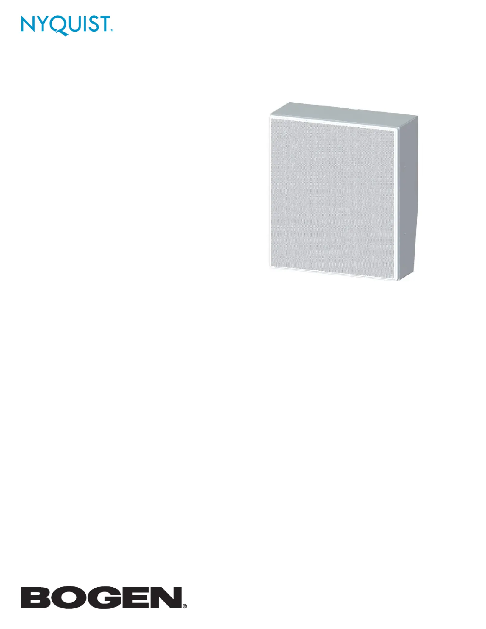
NQ-S1810WT-G3 Nyquist Gen-3 VoIP
Wall Bae Speaker
Installation and Use Guide

2
NQ-S1810WT-G3
With the Nyquist Series Gen-3 VoIP Wall Bae Speaker, there is no need to manually set or adjust external am-
pliers, traditional intercom wiring, or transformer taps. Connect the speaker via a Cat 5 or higher cable to a Pow-
er-Over-Ethernet (PoE) switch or PoE injector and it’s ready to use.
The speaker features an integrated 10W power amplier, a CAN Bus interface, a MEMS microphone for superior
talkback audio, and a Form C SPDT-type 2A dry contact relay for controlling or overriding third-party devices like
audio-visual sources.
The speaker also allows DHCP deployment for easy installation. You can let your Nyquist server automatically dis-
cover and congure your speaker, or you can manually congure it through the speaker’s web-based user interface
(web UI). The web UI also allows easy updating of rmware and setting of parameters for Digital Signal Processing
(DSP). For more information about the web UI, refer to the Nyquist Gen-3 VoIP Speakers Conguration Guide.
Speaker Layout
The layout of the speakers should be planned prior to installation.
Because wall bae speakers are designed to project forward, it is best to aim them all in the same direction, as
this provides for greater coverage and clarity. You can use the building’s roof pillars or other available supports for
mounting the wall baes.
In some cases, it may be necessary to mount the wall baes on opposing walls. In these cases, the speakers will
project sound in opposing directions.
Hallway
Wall bae speakers work well with rooms and hallways that are 20’ to 60’ wide.
Layout starts at one end of the hallway or room. The rst speaker should be
installed 10’ from the end of the hallway or room. The next speaker on that wall
should be installed 20’ from the rst speaker. Each additional speaker should be
installed 20’ apart from the previous one. The rst speaker on the opposing wall
should be installed 20’ from the end of the hallway or room, thereby staggering
the speakers. Each additional speaker should be installed 20’ apart from the pre-
vious one (see Figure 1).
Rooms
In most cases, an environment, such as a classroom, requires only a single wall bae speaker to service the entire
room. The nal placement of the speaker within the room can vary, but such common area locations as at the head
of the room or near the room entrance are typically chosen (see Figure 2).
Figure 2: Typical speaker position for a classroom.
Based on the speaker position that has been selected, you can choose between several mounting options, as
described below.
Figure 1: Hallway speaker layout.

3
NQ-S1810WT-G3
Speaker Installation
1. The speaker is packaged with the bae attached to the
enclosure, a grille, and two ush-mount brackets. Remove
the four screws that attach the speaker bezel to the
enclosure, then remove the cardboard insert from inside the
enclosure, as shown in Figure 3.
2. Select a mounting option from Figures 4–7 and use the
appropriate hardware for gang-box mount or wall mount.
Bogen provides the screws and washers for mounting on
a standard electrical gang box, but when mounting directly
to a wall or other surface, you must supply the appropriate
hardware for the specic wall/surface construction type
(e.g., concrete cinder block, metal beams, etc.).
NOTE: The wall mounting of the NQ-S1810WT-G3 should be conducted by trained professionals with sucient knowl-
edge and tools to t the wall-mount fasteners in a reliable way.
Figure 5: Flat wall mount (hardware not supplied;
tapping screws for concrete/brick shown)
Figure 6: Angled wall mount (hardware not supplied;
tapping screws for concrete/brick shown)
Figure 4: #6 screws and washers
for mounting to gang box.
3. When applicable, use the pluggable CAN bus connector to
attach one or more NQ-E7020 Digital Call Switches to the
Nyquist VoIP Module 820-00071-00, as shown in Figure 8.
4. If the CAN bus is to be used, ensure the CAN_H and CAN_L
use Cat 5 10/100 twisted pair cable.
5. To connect a third-party device to the dry contact relay out-
put, do one of the following:
a. If the device is looking for a Normally Open contact, connect the device using the NO and COM terminals.
b. If the device is looking for a Normally Closed contact, connect the device using the NC and COM terminals.
Figure 7: Flush mount (hardware supplied).
NQ-E7020 Digital
Call Switch
Figure 8: CAN bus connector with multiple digital call switches
Figure 3: Remove cardboard insert from enclosure.
Product specificaties
Merk: | Bogen |
Categorie: | Niet gecategoriseerd |
Model: | Nyquist NQ-S1810WT-G3 |
Heb je hulp nodig?
Als je hulp nodig hebt met Bogen Nyquist NQ-S1810WT-G3 stel dan hieronder een vraag en andere gebruikers zullen je antwoorden
Handleiding Niet gecategoriseerd Bogen
15 Juni 2025
15 Juni 2025
15 Juni 2025
23 Mei 2025
22 Mei 2025
21 Mei 2025
21 Mei 2025
21 Mei 2025
21 Mei 2025
21 Mei 2025
Handleiding Niet gecategoriseerd
- ICC
- TRIUS
- CaterCool
- BMB
- Walrus Audio
- AJH Synth
- Navionics
- Signature Hardware
- Anton/Bauer
- Intermec
- Diamex
- CELLFAST
- Aquadon
- Palmako
- Lexibook
Nieuwste handleidingen voor Niet gecategoriseerd
16 Juni 2025
16 Juni 2025
16 Juni 2025
16 Juni 2025
16 Juni 2025
16 Juni 2025
16 Juni 2025
16 Juni 2025
16 Juni 2025
16 Juni 2025