Black Lion Audio PBR TRS Handleiding


Lees hieronder de 📖 handleiding in het Nederlandse voor Black Lion Audio PBR TRS (2 pagina's) in de categorie Niet gecategoriseerd. Deze handleiding was nuttig voor 15 personen en werd door 2 gebruikers gemiddeld met 4.5 sterren beoordeeld

Pagina 1/2
Notice
This manual provides general information, preparation for use, installation and oper-
ating instructions for the Black Lion Audio PBR-Series Patchbays.
The information contained in this manual is subject to change without notice. Black
Lion Audio makes no warranties of any kind with regard to this manual, including, but
not limited to, the implied warranties of merchantability and tness for a particular
purpose. Black Lion Audio shall not be liable for errors contained herein or direct, indi-
rect, special, incidental, or consequential damages in connection with the furnishing,
performance, or use of this material.
©2022 Black Lion Audio. The Black Lion AudioLion Facelogo, BLA, are trademarks
or registered trademarks of Black Lion Audio.
This manual and any associated intellectual property are subject to
copyright protection. No part of this document may be reproduced in
any form without explicit written consent from Black Lion Audio.
Owners Manual
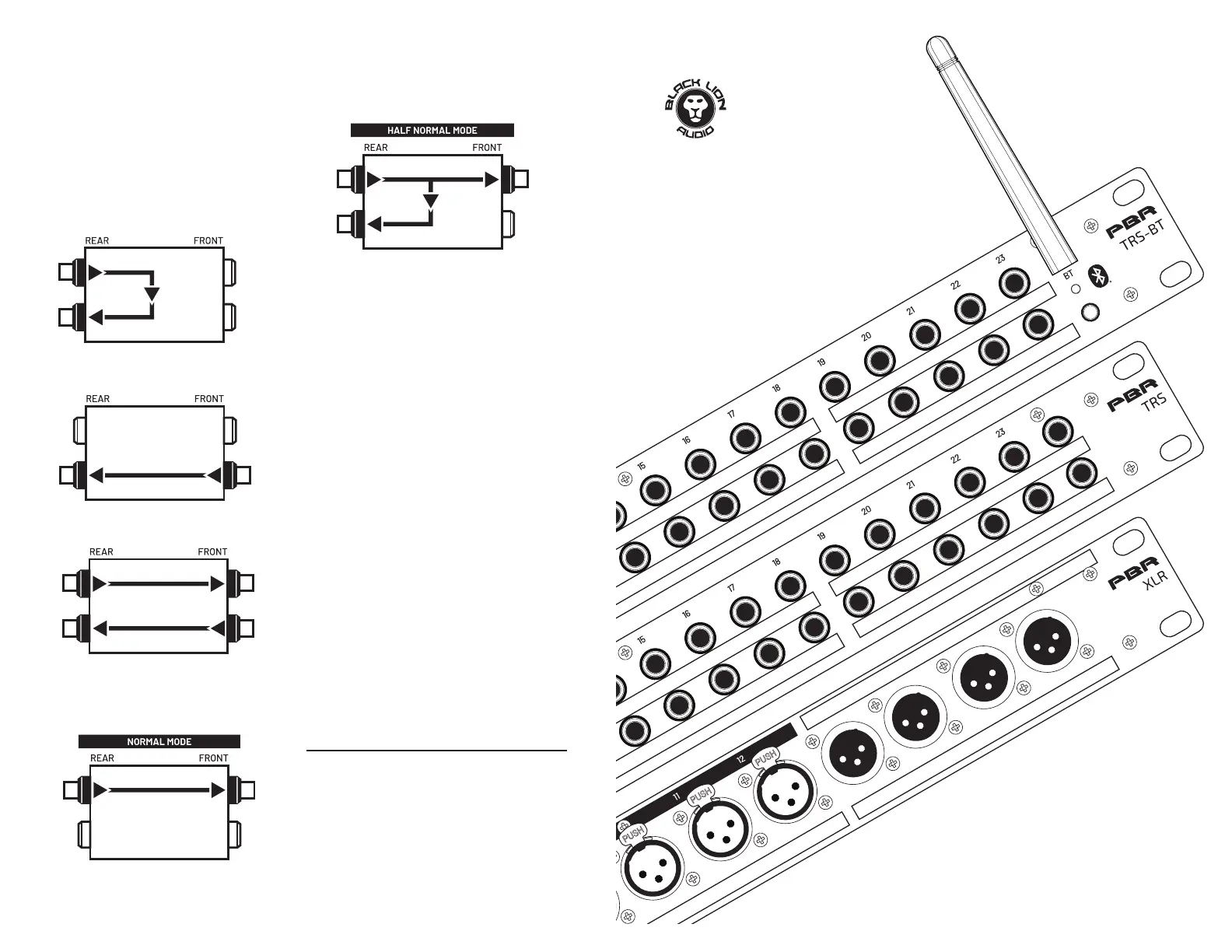
SIGNAL FLOW IN YOUR TRS PATCHBAY
The ow of signal through a patchbay module is affected by both
physical connections and mode setting (Normaled or Half-
Normaled.) The most common conguration for a patchbay is for
signals to come in to the patchbay from the top rear connections,
and out of the patchbay from the bottom rear connections.
Conversely, on the front of the patchbay, the top row connections
are outputs and the bottom row connections are inputs.
With jacks connected to the top rear and bottom rear of
a single patchbay module, signals coming into a top rear
connection are passed directly through to the output on the
bottom rear, as shown here. This connection style should
be used for your hardwares default conguration - the way
you want your signals toow on a day-to-day basis.
When no jacks are connected to the top connections of a module, a
signal from the front bottom input is passed through to the rear bottom
output.
When all four jacks are connected to a patchbay module, a signal
connected to a rear top input of the patchbay is passed to the front top
output, while signal from the the front bottom input is passed to the
rear bottom output.
NORMALED OPERATION
When a module is set to Normaled and connections are made to the
top rear and top front jacks, the signal is passed through from the
top rear to the top front - breaking the connection shown ingure 1.
A Normaled conguration allows you to run several devices in series by
using patch cables on the front of the patchbay to interconnect several
of your devices. For example, you could run a signal from a preamp, to a
compressor, and nally to a reverb. A cable inserted into the bottom
rear will have its connection connection broken when a cable is
inserted into the top front.
HALF-NORMALED OPERATION
When a module is set to Half-Normaled and connections are made
to the rear top, rear bottom, and front top jacks, the signal is passed
through from the top rear to the top front - without breaking the con-
nection shown in gure 1.
This allows you to use the patchbay as a mult (splitter), sending the signal
coming into the patchbay to two different destinations; very useful for
parallel processing of your signal and monitoring applications. Inserting
a cable in to the front bottom jack of a half-normaled module will break
the connection between the rear jacks.
TRS PATCHBAY TIPS
We advise against connecting a single device, interface, or outboard
processor to a single modules vertically-connected set of patch points.
In other words, don’t connect both the Input and Output of a delay unit on
module 1 of your patchbay - that would could create a feedback loop. Use
separate modules for a single devices inputs and outputs.
Furthermore, doing so severely limits the convenience of a patchbay. It
also forces you to use more patch cables, and increases the minimum
length of the signal chain. In reality it is more convenient to wire the
normalling scheme around the way that your particular studio is wired
and will most commonly be used, and to modify those connections by
breaking patches from the front of the patchbay when something other
than the “standard conguration for your studio is desired.
Based on our experience, basing patchbay wiring on thru connections
(without internal normaling) is quick and easy. That said, weve found
that using a normalled or half-normalled conguration based on the
most commonly-used processing chains in your studio saves a lot of
time in the long run.
We advise against running phantom power through a TRS patchbay, as
this makes it possible to send phantom power to a device not designed
to handle it; expensive damage could result!
Fig. 2
Fig. 1
Fig. 3
Fig. 4
Fig. 5
PBR-Series
Patchbays
PBR TRS
PBR TRS-BT
PBR XLR
The PBR TRS and PBR TRS-BT Patchbays both offer 96 points
of connectivity for your studio gear, allowing for permanent
installation and routing of your favorite hardware while still
allowing for exible and creative patching.
The PBR TRS and PBR TRS-BT Patchbays both offer Normalled and
Half-Normalled operation, switchable from the rear of the unit on a
per-module basis. A module, in this context, is any set of vertically-
aligned jacks on the patchbay; front and back.
The functionality of the PBR TRS and PBR-TRS-BT are identical,
apart from the Bluetooth connection available on the PBR TRS-BT,
discussed below.
A typical patchbay conguration will have device outputs sent to
the top rear row of patch points with device Inputs connected to
the rear bottom row. For example, you would connect the Input of
a delay unit or compresssor to a rear bottom row connection of the
patchbay, and its Output to a rear top row conection.
PBR TRS-BT BLUETOOTH
CONNECTION
Once you have installed your PBR TRS-BT where you need
it, plug it in to an appropriate power source. Note: The
power supply is only needed for Bluetooth audio.
Plug in your equipment to the correct outlets on the
PBR TRS-BT.
Once the power supply is pluged into the power inlet, the
PBR TRS-BT Bluetooth is active. To sync your device to the
PBR TRS-BT, press and hold the Bluetooth Sync button.
Once the Bluetooth Status LED has started to blink,
devices are able to nd the PBR TRS-BT via Bluetooth
connection.
To sync another device to the PBR TRS-BT, press and hold
the Bluetooth Sync button.
1. Power Inlet: Connect power supply here. Power is only
necessary for Bluetooth connection.
2. Bluetooth Sync: This button operates the Bluetooth
Sync. Press and hold this button to set the PBR TRS-BT
to sync mode, when connecting new devices.
3. Bluetooth Status: When this LED is blinking, the PBR
TRS-BT is ready to be paired. When this LED is lit, the
PBR TRS-BT is synced to a device.
4. Bluetooth Left Output: This TRS jack outputs the left
channel of the Bluetooth audio.
5. Bluetooth Right Output: This TRS jack outputs the right
channel of the Bluetooth audio.
1. Balanced 1/4 TRS connection: Accepts 1/4” jacks for connecting
and routing your audio gear. Accepts balanced (TRS) and unbal-
anced (TS) connections.
2. Normal/Half-Normaled Switch: Toggles the routing for the select-
ed channel between Normal and Half Normaled operation. Switch
in = Normal, Switch out = Half-Normal.
IMPORTANT SAFETY INSTRUCTIONS
1. Read these instructions.
2. Keep these instructions
3. Heed all warnings.
4. Follow all instructions.
5. Do not use this apparatus near water.
6. Clean only with dry cloth.
7. Install in accordance with the manufacturer’s instructions.
8. Do not install near any heat sources such as radiators, heat regis-
ters, stoves, or other apparatus that produce heat.
9. Do not defeat the safety purpose of the polarized or grounding-type
plug. A polarized plug has two blades with one wider than the other.
A grounding-type plug has two blades and a third grounding prong.
The wide blade or third prong is provided for your safety. If the pro-
vided plug does not t into your outlet, consult an electrician for
replacement of the obsolete outlet.
10. Protect the power cord from being walked on or pinched particular-
ly at plugs, convenience receptacles, and the point where they exit
from the apparatus. If the power cord becomes frayed, stop using
immediately.
11. Use only attachments/accessories specied by the manufacturer
12. Use only with a cart, stand, tripod, bracket or table specied by the
manufacturer, or sold with the apparatus. When a cart is used, use
caution when moving the cart/apparatus combination to avoid in-
jury from tip-over.
13. Unplug this apparatus during lightning storms or when unused for
long periods of time.
14. Refer all servicing to qualied service personnel. Servicing is re-
quired when the apparatus has been damaged in any way, such as
power supply cord or plug is damaged, liquid has been spilled or
objects have fallen into the apparatus, the apparatus has been ex-
posed to rain or moisture, does not operate normally, or has been
dropped.
15. This apparatus shall not be exposed to dripping or splashing, and
no object lled with liquids, such as vases, shall be placed on the
apparatus.
16. The mains plug or power inlet on the product is used as the discon-
nect device, so the disconnected device shall remain readily opera-
ble when reconnected.
17. Any changes or modications not expressly approved in this manu-
al could void your authority to operate this apparatus.
IMPORTANT !
The lightning ash with an arrowhead symbol within an equilateral tri-
angle is intended to alert the user to the presence of uninsulated “dan-
gerous voltage within the product’s enclosure that may be of sucient
magnitude to constitute a risk of electric shock to persons.
The exclamation point within an equilateral triangle is intended to alert
the user to the presence of important operating and maintenance
(servicing) instructions in the literature accompanying the product.
This product complies with all international standards for safety and
emissions including IEC62368 and FCC Part 15-B.
Do not attempt to service this unit yourself, as it will void your warran-
ty. Please check your unit carefully upon receipt and return to place
of purchase immediately if there are any problems with the product.
After that, the standard Black Lion Audio 3 YEAR warranty will apply
to defects in materials and workmanship.
U.S.A.
Should your Black Lion Audio product require service,
please contact us on our customer service site:
https://www.blacklionaudio.com/contact. You must obtain an RA #
(Return Authorization number) from us before shipping a unit back to
us. This RA # must be clearly written on the outside of the box.
Please safely pack the units…It is best to use the original packing
materials. Black Lion Audio cannot be responsible for any damag-
es incurred in shipping to us due to poor packaging. PLEASE PACK
CAREFULLY and FULLY INSURE THE SHIPMENT.
INTERNATIONAL
For service or warranty assistance, please contact the Black Lion Au-
dio distributor in your country through the dealer from whom you pur-
chased this product.
LIMITED 3 YEAR WARRANTY
Black Lion Audio’s PBR TRS Patchbays are warranted by Black Lion Au-
dio to be free from defects in materials and workmanship for the period
of THREE (3) YEARS to the original purchaser. In the event of such de-
fects, the product will be repaired without charge or, at our option, re-
placed with a new one if delivered to Black Lion Audio prepaid, together
with a copy of the sales slip or other proof of purchase date. The warran-
ty excludes problems due to normal wear, abuse, shipping damage or
failure to use the product in accordance with the specications.
All parts and labor are covered under this Limited Warranty. However,
if it is determined by Black Lion Audio that the device was damaged or
made defective through abuse, we reserve the right to charge the cus-
tomer for the cost of the repair.
Black Lion Audio shall not be liable for damages based upon inconve-
nience, loss of use of the product, loss of time, interrupted operation or
commercial loss or any other damages, whether incidental, consequen-
tial or otherwise. This warranty gives you specic legal rights, and you
may have other rights, which will vary from state to state.
This warranty is not transferable.
The PBR XLR patchbay offers 32 connection points for your equipment
with XLR connections. Connecting your gear to the XLR patchbay will
save a lot of time and frustration: no more getting behind your racks and
reconnecting hardware every time you want to try some new routing!
Simply connect the rear male jacks to the inputs of your racked
hardware, and the outputs of your racked gear to the rear female jacks.
From there, you can use the convenient front panels to directly connect
to any hardware connected to the rear of the patchbay.
PBR XLR
1. XLR female connection: Accepts male XLR jacks for connecting
your audio gear.
2. XLR male connection: Accepts female XLR jacks for connecting
your audio gear.
PBR TRS AND PBR TRS-BT
1
1
2
1
4
5
2
3
21


Product specificaties

Merk: Black Lion Audio
Categorie: Niet gecategoriseerd
Model: PBR TRS

Heb je hulp nodig?

Als je hulp nodig hebt met Black Lion Audio PBR TRS stel dan hieronder een vraag en andere gebruikers zullen je antwoorden


Handleiding Niet gecategoriseerd Black Lion Audio

Handleiding Niet gecategoriseerd

Nieuwste handleidingen voor Niet gecategoriseerd