Asrock Rack EC262D4-4L Handleiding
Bekijk gratis de handleiding van Asrock Rack EC262D4-4L (2 pagina’s), behorend tot de categorie Server. Deze gids werd als nuttig beoordeeld door 47 mensen en kreeg gemiddeld 4.5 sterren uit 6 reviews. Heb je een vraag over Asrock Rack EC262D4-4L of wil je andere gebruikers van dit product iets vragen? Stel een vraag
Pagina 1/2
EC266D4-4L
Quick Installation Guide
www.asrockrack.com
EC266D4-4L
2
P/N: 15G065341000AK V1.0
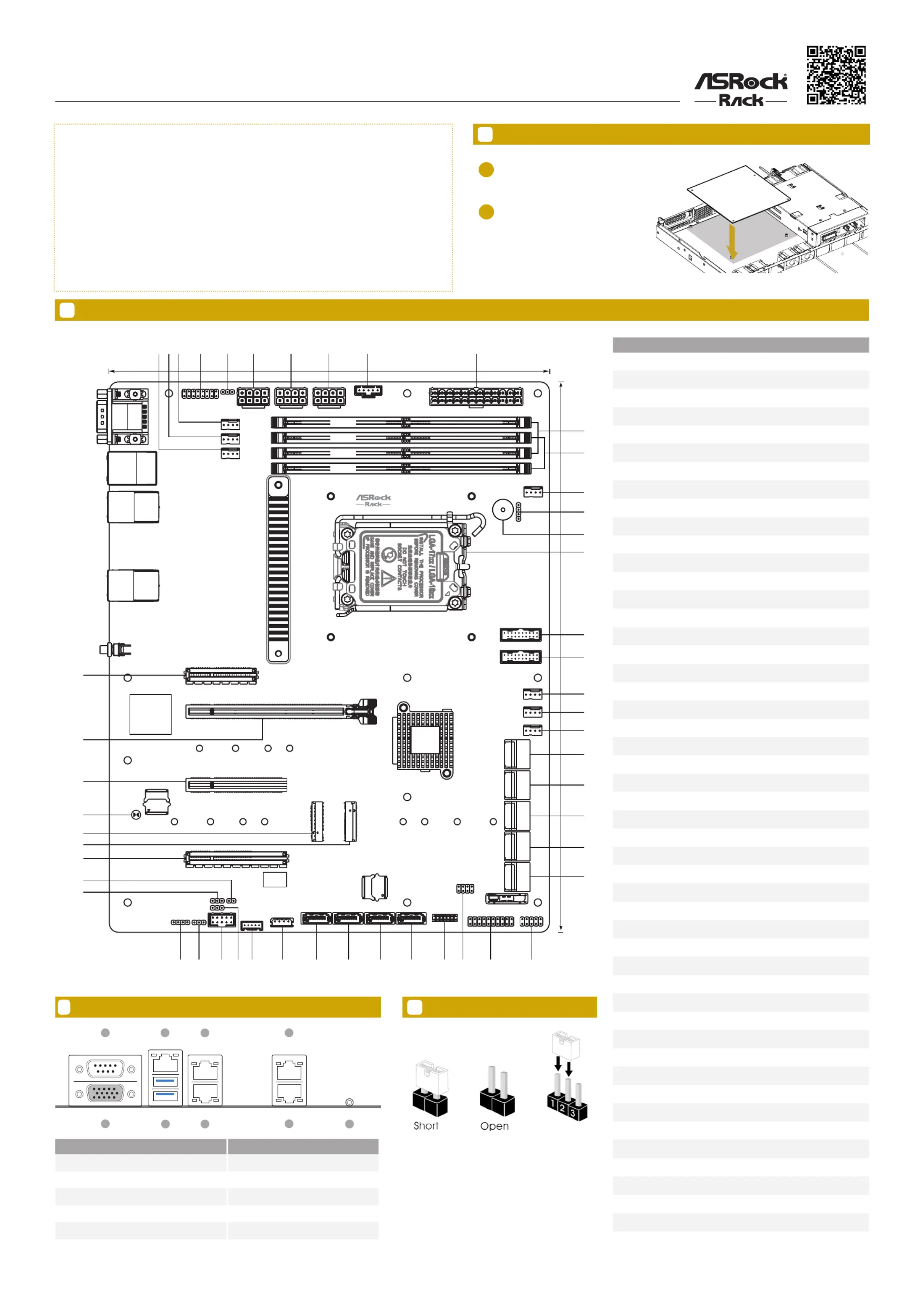
Motherboard Layout
The server board User's Manual is available for download from the ASRock Rack's ocial website
at http://www.asrockrack.com.
Take note of the following precautions before installing server board components or change any
server board settings.
1. Unplug the power cord from the wall socket before touching any components.
2. To avoid damaging the server board’s components due to static electricity, NEVER place the
server board directly on the carpet or the like. Also remember to use a grounded wrist strap or
touch a safety grounded object before handling the components.
3. Hold components by the edges and do not touch the ICs.
4. Whenever uninstall any component, place it on a grounded anti-static pad or in the bag that
comes with the component.
5. When placing screws into the screw holes to secure the server board to the chassis, please do
not over-tighten the screws! Doing so may damage the server board.
Install the Server Board1
Insert the server board into the chassis.
Ax the screws clockwise into the
mounting holes in all of the corners of
the server board.
Do not over-tighten the screws.
1
2
*15G065341000AK*
4
Jumper Cap On/O
When the jumper cap is placed on the pins, the
jumper is “Short”. If no jumper cap is placed on
the pins, the jumper is “Open”.
e illustration shows a 3-pin jumper whose pin1
and pin2 are “Short” when a jumper cap is placed
on these 2 pins.
SATA_4_5
SATA_SGPIO1
AUX_PANEL1
IPMB1
BMC_SMB1
BIOS
ROM
Dr.Debug
TPM_BIOS_PH1
EC266D4-4L
®
SATA_6_7
SATA_8_9
SATA_10_11
SATA_12_13
SATA_3
SATA_2
SATA_1
SATA_0
USB_1_2
PANEL1
BAT1
TR1NMI_BTN1
PECI1
SEC_OR1
LED_LAN3_4
PCIE2
PCIE4
PCIE6
PCIE7
BMC
ROM
CLRCMOS1
M2_2
M2_3
NUT30_3
NUT42_3
NUT60_3
NUT80_3
NUT80_2
NUT60_2
NUT42_2
NUT30_2
Intel
C266
ASPEED
ASR2600
UID1
LAN3
LAN4
LAN1
LAN2
USB3.2 Gen1
T:USB3_2
B:USB3_1
IPMI_ LAN
VGA
COM1
FAN5
FAN6
FAN7
ATX12V1
PWM_CFG1
FRNT_VGA1
ATX12V2ATX12V3
PSU_SMB1
ATXPWR1
BUZZER1
SPEAKER1
FAN4
USB3_5_6
USB3_1_2
FAN3
FAN2
FAN1
DDR5_B2
DDR5_B1
DDR5_A2
DDR5_A1
CPU1
24.4cm (9.6in)
30.5cm (12in)
1
783
3335
2
34
4
36
9
14
15
11
20
21
24
26
2730
25
16
18
22
23
2831
12
13
17
19
29
10
32
5
6
37383940
41
42
43
44
45
46
47
48
49
I/O Panel3
No.Description
1Chassis Fan Connector (FAN5)
2Chassis Fan Connector (FAN6)
3Chassis Fan Connector (FAN7)
4Front VGA Header (FRNT_VGA1)
5PWM Conguration Header (PWM_CFG1)
6ATX 12V Power Connector (ATX12V1)
7ATX 12V Power Connector (ATX12V2)
8ATX 12V Power Connector (ATX12V3)
9PSU SMBus Header (PSU_SMB1)
10ATX Power Connector (ATXPWR1)
112 x 288-pin DDR5 DIMM Slots (DDR5_A2, DDR5_B2)
122 x 288-pin DDR5 DIMM Slots (DDR5_A1, DDR5_B1)
13Chassis Fan Connector (FAN4)
14Chassis Speaker Header (SPEAKER1)
15BUZZER1
16LGA1700 CPU Socket (CPU1)
17USB 3.2 Gen1 Header (USB3_5_6)
18USB 3.2 Gen1 Header (USB3_1_2)
19Chassis Fan Connector (FAN3)
20Chassis Fan Connector (FAN2)
21Chassis Fan Connector (FAN1)
22SATA3 Connectors (SATA_4)(Lower), (SATA_5)(Upper)
23SATA3 Connectors (SATA_6)(Lower), (SATA_7)(Upper)
24SATA3 Connectors (SATA_8)(Lower), (SATA_9)(Upper)
25SATA3 Connectors (SATA_10)(Lower), (SATA_11)(Upper)
26SATA3 Connectors (SATA_12)(Lower), (SATA_13)(Upper)
27System Panel Header (PANEL1)
28Auxiliary Panel Header (AUX_PANEL1)
29SATA SGPIO Connector (SATA_SGPIO1)
30SPI TPM Header (TPM_BIOS_PH1)
31SATA3 Connector (SATA_3)
32SATA3 Connector (SATA_2)
33SATA3 Connector (SATA_1)
34SATA3 Connector (SATA_0)
35Intelligent Platform Management Bus Header (IPMB1)
36BMC SMBus Header (BMC_SMB1)
37CPU PECI Mode Jumper (PECI1)
38USB 2.0 Header (USB_1_2)
39Security Override Jumper (SEC_OR1)
40Front LAN LED Connector (LED_LAN3_4)
41ermal Sensor Header (TR1)
42Non Maskable Interrupt Button (NMI_BTN1)
43PCI Express 4.0 p1-x4 Slot (PCIE2)
44M.2 Socket (M2_3) (Type 2230/2242/2260/2280)
45M.2 Socket (M2_2) (Type 2230/2242/2260/2280)
46Clear CMOS Pad (CLRCMOS1)
47PCI Express 5.0 p1-x8 Slot (PCIE4)
48PCI Express 5.0 x16/x8 Slot (PCIE6)
49PCI Express 4.0 p1-x4 Slot (PCIE7)
2
6
3
5
17
4
8
9
No.No.DescriptionDescription
161G LAN RJ-45 Port (LAN2)VGA Port (VGA)
2Serial Port (COM1)71G LAN RJ-45 Port (LAN3)
3USB 3.2 Gen1 Ports (USB3_3_4)81G LAN RJ-45 Port (LAN4)
4LAN RJ-45 Port (IPMI_LAN) 9UID Switch (UID1)
51G LAN RJ-45 Port (LAN1, shared NIC)
Product specificaties
| Merk: | Asrock |
| Categorie: | Server |
| Model: | Rack EC262D4-4L |
Heb je hulp nodig?
Als je hulp nodig hebt met Asrock Rack EC262D4-4L stel dan hieronder een vraag en andere gebruikers zullen je antwoorden
Handleiding Server Asrock

20 Januari 2026
23 December 2025
22 December 2025
26 Augustus 2025
25 Augustus 2025
25 Augustus 2025
1 Juli 2025
1 Juli 2025
18 Maart 2025
18 Maart 2025
Handleiding Server
Nieuwste handleidingen voor Server
20 Januari 2026
20 Januari 2026
20 Januari 2026
20 Januari 2026
19 Januari 2026
3 Januari 2026
8 December 2025
8 December 2025
26 November 2025
26 November 2025