Artusi CAGH31B_ Handleiding
Bekijk gratis de handleiding van Artusi CAGH31B_ (2 pagina’s), behorend tot de categorie Fornuis. Deze gids werd als nuttig beoordeeld door 62 mensen en kreeg gemiddeld 4.5 sterren uit 9 reviews. Heb je een vraag over Artusi CAGH31B_ of wil je andere gebruikers van dit product iets vragen? Stel een vraag
Pagina 1/2
BUILT-IN GAS HOB
INSTALLATION AND USER INSTRUCTIONS
Note: Do not use the hob until you have read the instruction manual.
Reference to AS/NZS 5601
Cod:0070302047
1. INTRODUCTION
(*) Air inlet minimum section: 100cm
2
Fig. 1 Fig. 2 Fig. 3
UNPACKING THE APPLIANCE
Remove all packaging and make sure the appliance is in perfect condition.
If you have any doubts, do not use the appliance and call your supplier..
Some parts on the appliance are protected by a plastic film. This protective film must be removed
before the appliance is used.
Unit: mm
Fig. 4
Fig. 5
1
2
3
Even if you have used a gas hob before, it is important that you read these instructions thoroughly
before using the appliance, paying particular attention to the installation and safety instructions. If you
have any problems installing, operating or cooking with your hob, please check through these
instructions to ensure all of them have been adhered to.
WARNING! For your own safety, make sure that these instructions on installation, use and
maintenance are followed.
Please keep these instructions in a safe place for future reference.
Should the appliance be sold or transferred, please pass on these instructions to the new owner.
E
E
3. CLEANING AND MAINTENANCE
4. SAFETY INSTRUCTIONS
Make sure that this instruction booklet is read thoroughly and understood before attempting to install or
operate this hob.
The instructions are provided in the interest of your safety.
GAS SAFETY REGULATIONS AND USE OF YOUR HOB
1. It is a legal requirement that all gas appliances are installed by qualified personnel only in accordance
with current legislation. It is your responsibility to ensure compliance with the law.
2. Repairs or servicing of this product must only be carried out by an authorised service agent using
approved parts.
3. No attempt must be made to modify this appliance under any circumstances.
4. Cooking appliances can become very hot in use – please keep children and pets away from them.
5. Do not allow children to operate or play with any part of the appliance.
6. Do not use unstable pans and ensure that the handle is positioned away from the edge of the worktop.
7. In the interest of hygiene and safety, please ensure the hob is kept clean.
8. This appliance is designed for domestic cooking only. Commercial use will invalidate the warranty.
9. Do not cover the hob or place combustible materials on or near the surface even when the hob is not in
use.
10. Do not fill deep fat frying containers more than one third full of oil and NEVER leave unattended.
11. Before cleaning the hob, switch off at the mains.
12. When cooking is finished, switch off all controls and allow to cool.
13. These appliances are not intended for use by persons (including children) with reduced physical,
sensory or mental capabilities, or lack of experience and knowledge, unless they have been given supervision
or instruction concerning use of the appliance by a person responsible for their safety.
14. If the supply cable is damaged, it must be replaced by the authorised service agent or qualified person only.
15. Do not immerse the appliance or the power cable into water or any other liquid.
16. DO NOT SPRAY AEROSOLS IN THE VICINTY OF THIS APPLIANCE WHILE IT IS IN OPERATION.
17. DO NOT USE OR STORE FLAMMABLE MATERIALS ON OR NEAR THIS APPLIANCE.
18. DO NOT PLACE ARTICLES ON OR AGAINST THIS APPLIANCE.
19. DO NOT MODIFY THIS APPLIANCE.
5. INSTALLATION INSTRUCTIONS
TECHNICAL INFORMATION
The installation, adjustments, conversions and maintenance listed in this section must be carried out by
qualified personnel only.
The safety and automatic adjustment devices of the appliance may only be modified by an authorised service
agent.
The installation of this gas hob must comply with Australia and New Zealand standards.
This appliance must be fitted in compliance with the installation rules given above. Also, particular attention
must be given to the following requirements for ventilation.
INSTALLATION LOCATION
The appliance may be located in a kitchen, kitchen/diner or utility room, however, it cannot be in a
room containing a bath or shower.
WARNINGS
Comply with the following instructions, before remounting the parts:
-Check that the heads burners and the relative burner caps, are correctly positioned in their
housings.
-Check that burner head slots have not become clogged by foreign bodies.
-If to happened installation or after a few fimes, you find a tap is difficult to open or close do
not force it but call for techniacl assistance urgently.
-After use, to keep them in good condition, the plates should be treated with specific
products, easily found in the shops, to keep the surfaces clean and shining. This will also
prevent rust from forming.
-If any liquid spills over it must always be removed with a sponge.
VENTILATION RECOMMENDATION
The room must have an opening window or equivalent, some rooms may also require a permanent
vent. If the room has a volume between 5-10m
3
, it will require an air vent of 50cm
2
effective area,
unless it has a door which opens directly to the outside. If the room has a volume of less than 5m
3
, it
will require an air vent of 100cm
2
effective area (Fig. 1).
When using more than one hotplate at once, open a window if a mechanical extractor is not present or
working (Fig. 3).
The packaging materials should be carefully discarded and not left within easy reach of children as they
are a potential hazard.
INSTALLING AND FIXING THE HOB (QUALIFIED PERSONNEL ONLY)
The appliance can be fitted to any worktop with a thickness of 40mm or 50mm.
No overhanging surface or cooker hood should be closer to the hob than 750mm.
Fix the appliance in position (Fig. 4). The sides of the adjacent cabinets above may be lower than
750mm down to 650mm, provided they are heat and steam resistant.
These hobs are supplied with a special seal which prevents liquids from seeping underneath the
appliance. Follow these instructions in order to correctly fit this seal:
Detach the seals from their backing ensuring that the transparent protection still adheres to the seal.
Turn the hob over and correctly position seal *E* (Fig. 5) under the edge of the hob so that the outer
part of the seal perfectly matches the outer edge of the hob. The ends of the strips must fit together
without overlapping. Fix the seal to the hob evenly and securely, pressing it firmly in place.
CAGH1
CAGH1
3.6 MJ/h
6.3 MJ/h
6.3 MJ/h
Triple flame
gas burner
13.7 MJ/h
Semirapid
gas burner
Semirapid
Auxiliary
gas burner
gas burner
The surface of the hob need to be cleaned after each time they used.
Dayly cleaning
VITREOUS ENAMEL
ALUMINIUM
Hotplate burner bodies.
Similar to paint cleaning above. Use a nylon brush to remove any cleaning materials, water or dirt
from the hotplate burner bodies. After cleaning, wipe dry and refit to the hob ensuring they are
correctly seated.
Check parts are reassembled correctly by lighting the burners and allowing to dry out.
PLASTIC
Control knobs.
Wipe with a cloth wrung out in hot soapy water.
STAINLESS STEEL
Cloth wrung out in hot soapy water
Never clean when the top and components are still warm.Do not use metal or abrasive pads,abrasive
powders or corrosive spray products.Never leave vinegar,coffee,milk,salty water,lemon or tomato
juice for any length of time on the surfaces.
Hotplate、 burner caps、 pan supports、enamelled burner
caps (C)and burner heads (T)See right figure.
Cloth wrung out in hot soapy water. Stubborn stains.can be
removed with a cream paste.
approved by the Vitreous Enamel Development Council, liquid
cleaner or by rubbing with fine steel wool soap pads.
NOTE: The pan supports can also be cleaned in the
dishwasher.
CAGH95X
CAGH75X
CAGH75X
CAGH95X
Triple flame
gas burner
13.7 MJ/h
Triple flame
gas burner
13.7 MJ/h
10.8 MJ/h
Rapid
gas burner
3.6 MJ/h
Auxiliary
gas burner
6.3 MJ/h
Semirapid
gas burner
6.3 MJ/h
Semirapid
gas burner
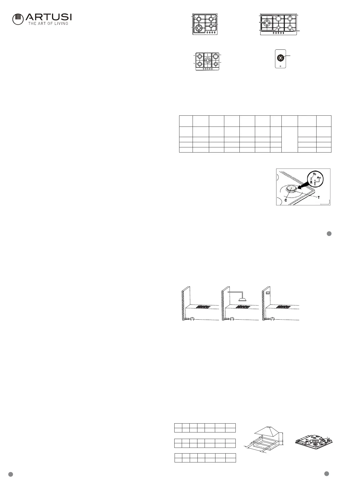
2. YOUR HOB
Applicable for Gas
Rapid
gas
burner
Semi-rapid
gas
burner
burner
Auxiliary
gas
Material
Flame
failure
device
Power
Supply
Size
(mm)
Built-in
(mm)
Type
500x580x90
500x860x90
500x680x90
AC
220-240 V
50-60Hz
/
///
Yes
Triple flame
gas burner
Stainless
steel
13.7 MJ/h6.3 MJ/h3.6 MJ/h477x557
477x557
Yes
Stainless
steel
13.7 MJ/h10.8 MJ/h6.3 MJ/h3.6 MJ/h
Yes
Yes
Stainless
steel
Glass
13.7 MJ/h
13.7 MJ/h
10.8 MJ/h6.3 MJ/h3.6 MJ/h
477x837
CAGH1
CAGH95X
CAGH1
CAGH95X
Triple flame gas burner 13.7 MJ/h
10.8 MJ/h
Rapid
gas burner
3.6 MJ/h
Auxiliary
gas burner
6.3 MJ/h
Semirapid
gas burner
6.3 MJ/h
Semirapid
gas burner
CAGH75X
CAGH31B
CAGH31B
CAGH75X
CAGH600CIX
CAGH600CIX
CAGH600CIX
CAGH600CIX
CAGH600X
CAGH600X
CBH460SS
CAGH31B
CBH460SS
CBH460SS
CAGH600X
CAGH600XCBH460SS
303x520x100287x498
A
B
D
C
E
E
G F
A B C D E F G
557 477 65 62
150min 90min 750min
A B C D E F G
837 477 65 62
150min 90min 750min
A B C D E F G
287 498 65 62
150min 90min 750min
CAGH31B
Product specificaties
| Merk: | Artusi |
| Categorie: | Fornuis |
| Model: | CAGH31B_ |
Heb je hulp nodig?
Als je hulp nodig hebt met Artusi CAGH31B_ stel dan hieronder een vraag en andere gebruikers zullen je antwoorden
Handleiding Fornuis Artusi

30 Oktober 2025
27 Oktober 2025
31 Maart 2025
5 Februari 2025
3 Juli 2024
7 Mei 2024
18 Maart 2024
6 Maart 2024
6 Maart 2024
6 Maart 2024
Handleiding Fornuis
Nieuwste handleidingen voor Fornuis
8 Juni 2026
8 Juni 2026
8 Juni 2026
8 Juni 2026
3 Juni 2026
2 Juni 2026
2 Juni 2026
2 Juni 2026
1 Juni 2026
31 Mei 2026