Anthro Fit Adjusta Handleiding

Anthro Bureau Fit Adjusta

Lees hieronder de 📖 handleiding in het Nederlandse voor Anthro Fit Adjusta (4 pagina's) in de categorie Bureau. Deze handleiding was nuttig voor 18 personen en werd door 2 gebruikers gemiddeld met 4.5 sterren beoordeeld

Pagina 1/4
R
Questions? 1-800-325-3841
Thank you for buying our Products!
Please return the enclosed Registration Card to receive our product
updates, new catalogs, and sale flyers.
Anthro Corporation Technology Furniture®
10450 SW Manhasset Drive
Tualatin, Oregon 97062
anthro.com
Anthro Corporation Technology Furniture® 10450 SW Manhasset Drive Tualatin, Oregon 97062 anthro.com
SAVE THESE INSTRUCTIONS! Rev. C January 2006
Hello! Thank you for choosing Anthro.
Before beginning assembly of your Adjusta Unit, take a moment to review the parts listed on the next page
to verify that your shipment is complete. Please review the assembly instructions of all Anthro products you
purchased and are planning to include in this installation, prior to beginning this assembly.
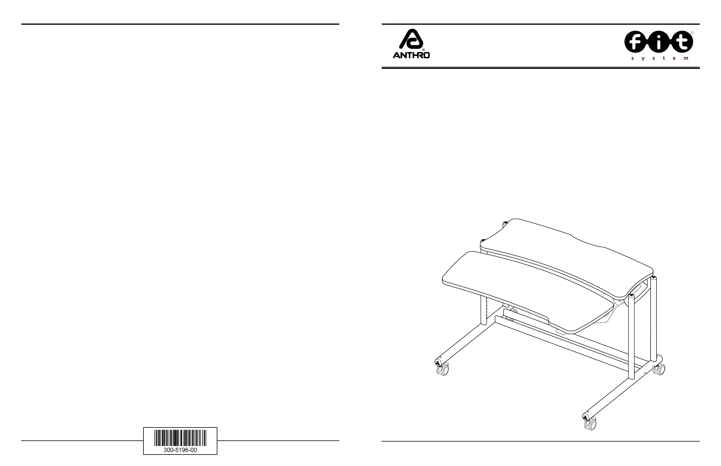
30”/36”/48” wide Adjusta Unit
Assembly Instructions
1-800-325-3841
To make the assembly of your Adjusta Unit even easier, we have included all of the required tools. The handy
Hex Driver Bit can be used in your electric drill in place of the Hex Driver. Your Adjusta Unit is heavy! A second
person will make this assembly procedure much easier.
Hex Driver 5/32............................................................ 375-5000-00
Hex Driver Bit 5/32..................................................... 375-5003-00
Hex Key 5/32................................................................. 375-5016-00
Hex Key 3/16................................................................. 375-5028-00
3-Way Wrench ............................................................. 225-5196-03
8 oz. Rubber Mallet ..................................................... 375-5022-00
Anthro Corporation Technology Furniture® 10450 SW Manhasset Drive Tualatin, Oregon 97062 1-800-325-3841 anthro.com
01fit Adjusta Fixed Worksurface Qty. 1 ....................... (see below)
30” Wide Fixed Worksurface (FAJ30zz/xx3) ....100-6454-00
36” Wide Fixed Worksurface (FAJ36zz/xx3) ....100-6455-00
48” Wide Fixed Worksurface (FAJ48zz/xx3) ....100-6456-00
02–t Adjusta Caddy Worksurface Qty. 1 ....................... (see below)
30” Wide Caddy Worksurface (FAJ30zz/xx3)..100-6458-00
36” Wide Caddy Worksurface (FAJ36zz/xx3) ..100-6459-00
48” Wide Caddy Worksurface (FAJ48zz/xx3) ..100-6460-00
03– Adjusta Mechanismfit ...............Qty. 1 ....................... (see below)
(The Adjusta Mechanism is packaged separately & requires assembly)
30” Wide Adjusta Mechanism (FAJ30zz/xx3) ...225-5545-00
36” Wide Adjusta Mechanism (FAJ36zz/xx3) ...225-5546-00
48” Wide Adjusta Mechanism (FAJ48zz/xx3) ...225-5547-00
04– Small Support Bracket X .............Qty. 1 ...................225-2014-00
05– 24.875” Vertical Legs .................Qty. 4 ...................125-5230-00
06– Adjusta Base Tubes ......................Qty. 2 ..................125-5276-00
07– Cross Tubes ....................................Qty. 2 ....................... (see below)
30” Wide Cross Tube (FAJ30zz/xx3) ...................125-5219-00
36” Wide Cross Tube (FAJ36zz/xx3) ...................125-5220-00
48” Wide Cross Tube (FAJ48zz/xx3) ...................125-5214-00
08– Insert Screws .................................Qty. 4 ...................325-5052-00
09– 2.0” Large End Caps ...................Qty. 4 ...................175-5157-00
10– Caster Inserts ...............................Qty. 4 ...................525-5032-00
11– 3” Locking Casters ......................Qty. 2 ...................150-5053-00
12– 5/16-18 Boltsfit ..............................Qty. 8 ...................325-5194-00
13– Tube Washersfit .........................Qty. 8 ..225-2050-00 or 225-3522-00
14– 3” Non-Locking Casters ........... Qty. 2 ...................150-5052-00
15– 3/4Wood Screws ........................Qty. 42 ................325-5106-00
16– Back Trough .................................... Qty. 1 ....................... (see below)
30” Wide Back Trough (F3029zz/xx3) ................225-2290-00
36” Wide Back Trough (F3629zz/xx3) ................225-2291-00
48” Wide Back Trough (F4829zz/xx3) ................225-2292-00
17– Support Screws ............................Qty. 8 ...................325-5010-00
18– Small Support Bracket Y ............Qty. 1 ...................225-2015-00
19– 1/4-20 Button Head Screws ......Qty. 4 ...................325-5003-00
20– 1.5” Small Caps .............................Qty. 4 ...................175-5156-00
All Fastener quantities listed here are the minimum needed
for your Adjusta Unit assembly. There may be a few extra
Fasteners included, which are not counted in the Parts List.
Component list for part #s FAJ30zz/xx3, FAJ36zz/xx3 & FAJ48zz/xx3
NOTE: Detailed views of all Hardware are provided with each Assembly Step.
05
07
08
03
02
10 12
06
01
09 13 14
15 16
17
20
11
18
04
19
19
Step 12
Align the Base Assembly on the Vertical Tubes as shown.
Secure the Base Assembly by inserting a Bolt through a fit
Tube Washer. Then insert the Bolt through the Base Tube
and carefully thread it into the Vertical Tubes.
Repeat for the remaining three Bolts and tighten all Bolts.
(5/16-18 X 3.5”) Boltfit
325-5194-00
fit Tube Washer
225-2050-00 or 225-3522-00
Locking Casters
fit Bolt
fit Tube
Washer
1.5” Small
End Cap
Rotate Knobs
to adjust
Caddy angle.
Squeeze Paddle
to adjust Caddy height.
Step 13
Insert the four 1.5” Small End Caps into the Vertical Legs.
Congratulations! Your assembly is complete.
Please return the enclosed Registration Card to receive
our product updates, new catalogs, and sale flyers.
Thank you for choosing Anthro!
Adjust the Caddy Worksurface height by:
1. Squeezing and holding the Paddle.
2. Reposition the Caddy to the desired location.
3. Release the Paddle.
Adjust the Caddy Worksurface angle by:
1. Rotating the Knobs counterclockwise.
2. Reposition the Caddy to the desired angle.
3. Rotate the Knobs clockwise.
Step 9 (requires Worksurface to be 12” from floor)
Rotate the Caddy Worksurface so the predrilled holes face
upward and the Lip faces the front of the Adjusta Unit.
Slide the Caddy under the Mechanism and align
the three holes located on each end of the Caddy and
Mechanism.
Secure the Caddy using a total of six Wood Screws. Then,
secure the Paddle to the Caddy using four Wood Screws.
NOTE: Make certain the Cable for the Paddle is positioned
underneath the Adjusta Bar.
Anthro Corporation Technology Furniture® 10450 SW Manhasset Drive Tualatin, Oregon 97062 1-800-325-3841 anthro.com
Step 2 (uses the 3-Way Wrench)
Unpack the remaining Adjusta Mechanism components
and arrange them as shown at right.
Place one Crossbar end onto the lower Crossbar
Button and Threaded Bolt (located on each of the Arm
Mechanisms). Secure the Crossbar to the Arm Mechanism
using one 5/16 Hex Nut onto the Threaded Bolt.
Repeat for remaining Crossbar end and Arm Mechanism.
5/16” Hex Nut
(included with 225-554x-00) DETAIL VIEW
Arm Mechanism
Thread-
ed Bolts
5/16 Hex
Nut
Paddle
Brake/Paddle As-
sembly
Arm Mechanism Crossbar
Lower Crossbar
Button
NOTE: it is very important that you attach the
Crossbar ONLY to the Lower Crossbar Button.
Step 1a
Your Adjusta Mechanism comes unassembled and is
boxed separately inside the Adjusta Unit package.
Begin to assemble the Mechanism by first locating the Adjusta
Crossbar and Brake/Paddle Assembly, position it as shown at
right. Depress the Paddle once to free the Brake Shaft.
Place the Brake Shaft between the two center Crossbar
Flanges. Insert the Post through both center Crossbar
Flanges and Brake Shaft.
Cotter Pin
(included with 225-554x-00)
Center Crossbar Flanges
Cotter Pin
Step 1b
Install the Cotter Pin through the single opening of the
Post to secure into place.
NOTE: included with Adjusta Mechanism is a small bag of
Hardware containing the (1) Post, (1) Cotter Pin, (2) Hex
Nuts, (2) Wood Screws, & (2) Cable Mounts.
Post
(included with 225-554x-00)
Brake Shaft
Brake/Paddle Assembly
Crossbar
Post
3/4 Wood Screw
325-5106-00
Step 10
Install two Caster Inserts into each Base Tube and se-
cure with one Insert Screw per Insert.
Insert one Locking and one Non-Locking Caster into
each Insert of a Base Tube as shown.
Insert two End Caps into the ends of both Base Tubes.
Insert Screw
(with pink threads)
325-5052-00
Locking
Caster
Caster Inserts placed
into the large holes
Leave these two side holes open
Non-Locking
Caster
Paddle
Adjusta Bar
(12” high surface shown shaded)
FAJ30zz/xx3, FAJ36zz/xx3 & FAJ48zz/xx3
Step 11
Attach a Cross Tube to a Base Tube by inserting a Bolt fit
through a Tube Washer, then insert the Bolt through the
Base Tube and carefully thread into the Cross Tube.
Repeat this procedure for other Cross Tube. Then tighten
all Bolts. fit
fit Tube Washer
225-2050-00 or 225-3522-00
Cross Tube
fit Tube
Washer
(5/16-18 X 3.5”) Boltfit
325-5194-00
fit Bolt
Base Assembly
Wood Screw


Product specificaties

Merk: Anthro
Categorie: Bureau
Model: Fit Adjusta
Kleur van het product: Grey, Silver
Breedte: 1505 mm
Diepte: 927 mm
Hoogte: 793.7 mm
Maximale gewichtscapaciteit: 68 kg

Heb je hulp nodig?

Als je hulp nodig hebt met Anthro Fit Adjusta stel dan hieronder een vraag en andere gebruikers zullen je antwoorden


Handleiding Bureau Anthro

Handleiding Bureau

Nieuwste handleidingen voor Bureau