Anthro Fit Console Unit Handleiding
Bekijk gratis de handleiding van Anthro Fit Console Unit (4 pagina’s), behorend tot de categorie Bureau. Deze gids werd als nuttig beoordeeld door 52 mensen en kreeg gemiddeld 4.5 sterren uit 9 reviews. Heb je een vraag over Anthro Fit Console Unit of wil je andere gebruikers van dit product iets vragen? Stel een vraag
Pagina 1/4
R
Questions?
1-800-325-3841
Anthro
Corporation Technology Furniture
®
10450 SW Manhasset Drive Tualatin, Oregon 97062 anthro.com
SAVE THESE INSTRUCTIONS!
Rev. F January 2006
Hello! Thank you for choosing Anthro.
Before beginning assembly of your Console Unit, take a moment to review the parts listed on the next page
to verify that your shipment is complete.
Please review the assembly instructions of all Anthro products you
purchased and are planning to include in this installation, prior to beginning this assembly.
Your Console Unit is heavy!
A second person will be needed for this assembly procedure.
To make the assembly of your Console Unit even easier, we have included all of the required tools. The handy
Hex Driver Bit can be used in your electric drill in place of the Hex Driver.
Hex Driver
5
/
32
”
............................................................
375-5000-00
Hex Driver Bit
5
/
32
”
.....................................................
375-5003-00
Hex Key
5
/
32
”
.................................................................
375-5016-00
Hex Key
1
/
4
”
..................................................................
375-5024-00
3-Way Wrench
.............................................................
225-5196-03
8 oz. Rubber Mallet
.....................................................
375-5022-00
Console Unit
Assembly Instructions
1-800-325-3841
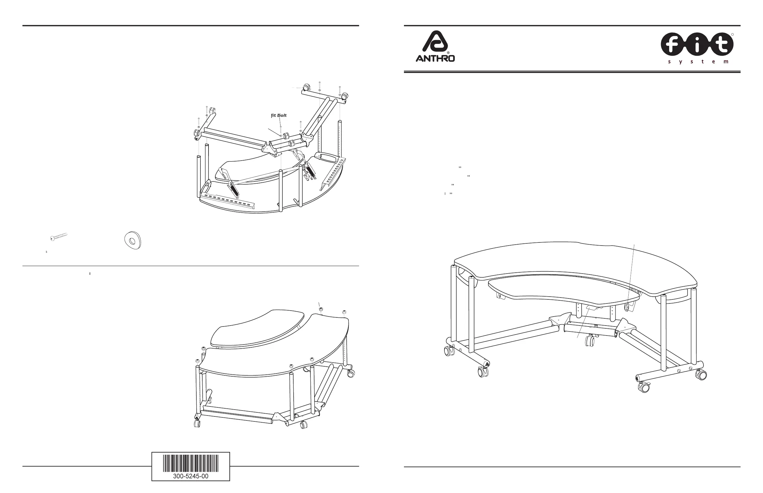
Step 15
Begin by placing the Base Tube Assembly
(Locking Casters
as shown)
onto the Vertical Legs.
Attach the Base Tubes to each Leg by inserting a
fi t
Bolt through a Tube Washer, then insert the
fi t
Bolt
through the Base Tube and carefully thread into
each Vertical Leg.
Tighten all
fi t
Bolts and Cap Screws.
Step 16
(uses the
1
/
8
” Hex Key)
Carefully rotate your Console Unit onto the Casters.
Pop the six Small End Caps into the Leg ends.
Congratulations!
Your assembly is complete.
(
5
/
16
-18 X 3.5”)
fi t
Bolt
325-5194-00
fi t
Tube Washer
225-2050-00 or 225-3522-00
fi t Tube Washer
fit Tube Washer
Locking Casters
Small End Caps
Adjust the Caddy Shelf height by:
1. Squeezing and holding the Paddle.
2. Reposition the Caddy to the desired location.
3. Release the Paddle.
Rotate Knob to
adjust Caddy
angle.
Squeeze Paddle
to adjust Caddy
height.
angle.
Adjust the Caddy Shelf angle by:
1. Rotating the Knob counterclockwise.
2. Reposition the Caddy to the desired angle.
3. Rotate the Knob clockwise.
Adjusting your Console Caddy
Product specificaties
| Merk: | Anthro |
| Categorie: | Bureau |
| Model: | Fit Console Unit |
| Kleur van het product: | Zwart |
| Breedte: | 1930.39 mm |
| Diepte: | 1149.35 mm |
| Hoogte: | 787.4 mm |
| Maximale gewichtscapaciteit: | 68 kg |
| Paneelmontage-interface: | Nee mm |
| Draaihoek: | 360 ° |
| Afmetingen (B x D x H): | 1930.39 x 1149.35 x 787.4 mm |
| Bereik kantelhoek: | 0 ° |
| Lift: | 0 cm |
Heb je hulp nodig?
Als je hulp nodig hebt met Anthro Fit Console Unit stel dan hieronder een vraag en andere gebruikers zullen je antwoorden
Handleiding Bureau Anthro

8 Februari 2024
8 Februari 2024
8 Februari 2024
8 Februari 2024
8 Februari 2024
8 Februari 2024
8 Februari 2024
8 Februari 2024
8 Februari 2024
8 Februari 2024
Handleiding Bureau
Nieuwste handleidingen voor Bureau
13 Juli 2026
12 Juli 2026
9 Juli 2026
8 Juli 2026
7 Juli 2026
7 Juli 2026
7 Juli 2026
7 Juli 2026
15 Juni 2026
3 Juni 2026