AMX NMX-ENC-N1115-WP Handleiding

AMX Niet gecategoriseerd NMX-ENC-N1115-WP

Lees hieronder de đź“– handleiding in het Nederlandse voor AMX NMX-ENC-N1115-WP (2 pagina's) in de categorie Niet gecategoriseerd. Deze handleiding was nuttig voor 23 personen en werd door 2 gebruikers gemiddeld met 4.5 sterren beoordeeld

Pagina 1/2
QUICK START GUIDE
SVSI N1115 MPC Series Wallplate Encoder
Overview
The N1115 Decor Style Wallplate Encoder is part of the SVSI N1000 MPC (Minimum
Proprietary Compression) Series and used in conjunction with N1000 MPC Series
Decoders (N1222 or N1233) for transmission of HDMI or analog video over Ethernet.
All Encoders and Decoders of the N1000 MPC Series feature input and output scaling,
balanced audio, HDMI video connection, and Power-over-Ethernet (PoE).
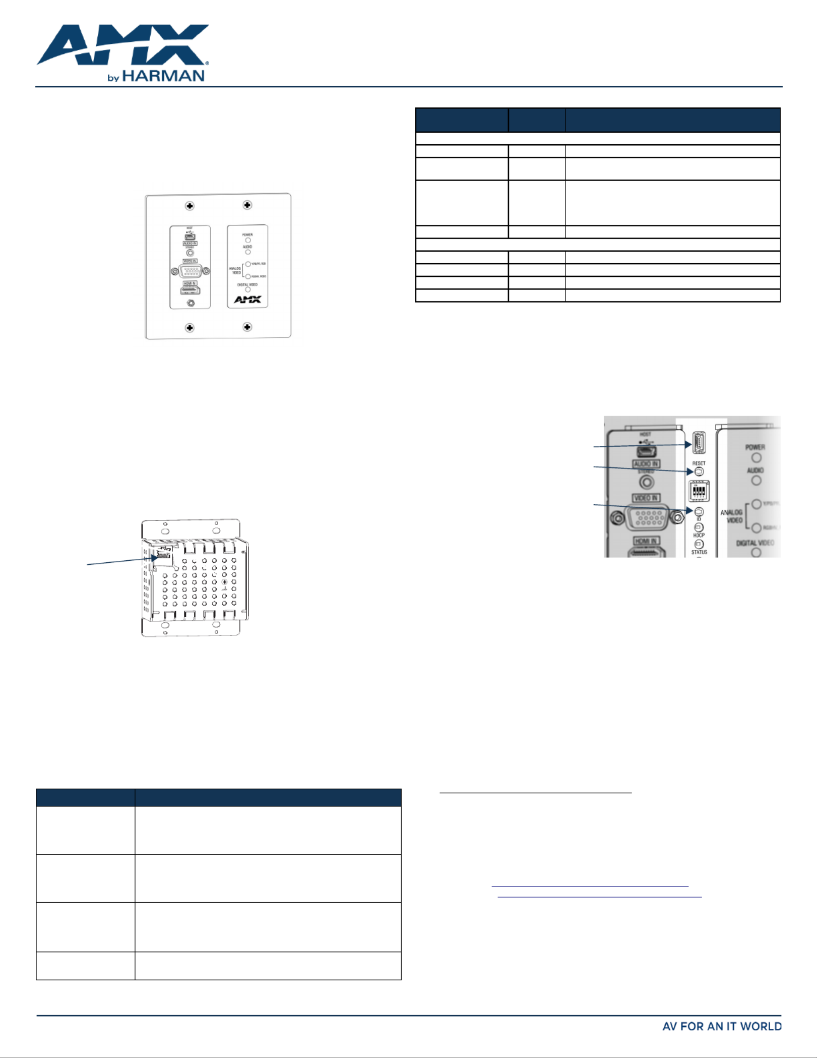
FIG. 1 N1115 WALLPLATE ENCODER
Installing the N1115 Wallplate Encoder:
Follow the steps below to mount your new N1115 MPC Encoder into an existing dual
gang electrical box.The instructions given assume the box is already installed with
Ethernet access running to it.
1. Connect the PoE-enabled Ethernet cable to the rear connector of the N1115 MPC
Encoder. This provides both network and power connection to the Encoder.
2. Place the N1115 MPC Encoder display into the box and secure it with four screws
(included in shipment).
3. Check LEDs for normal display (see the LED table at right).
4. Attach the (customer-provided) front cover plate to the unit to complete
installation.
Attaching Signal and Control Cables
The following table explains how to attach cables to the front of the Encoder. Keep in
mind that, by default, the HDMI connection has precedence for signal transmission. To
transmit either analog video or analog audio without detaching the HDMI connector, the
Encoder’s precedence settings must be changed on the page. Settings
IMPORTANT: Encoders must be securely mounted and connected to the switch before
attaching the remaining cables.
Basic Cabling Guidelines
This table shows LED states on initial power up. If not normal, check connections.
* The LEDs for DIGITAL VIDEO ANALOG VIDEO AUDIO , , and each indicate the
configured state of the connectors (not necessarily the presence of signals through the
Encoder).
** When an analog video signal is being received from the source device, only one of the
two LEDs will be green at any time.ANALOG VIDEO
Additional Buttons and Port
The front-center section of the unit is shown in FIG. 3. This section is covered by the
cover plate once it has been installed.
Establishing Connection
Before using your N1115 MPC Encoder, it must be configured using the free N-Able
setup utility software. However, you will not be able to configure units until they are in
the same subnet as the host computer. N-Series devices are shipped in Auto-IP mode
with a default IP address of 169.254.xxx.xxx. The sample steps below show how the
required changes (to the host computer’s IP settings) are made in a Windows
environment.
Steps for IP address configuration:
1. From the Control Panel > Network and Internet Network and dialog box, select
Sharing Center.
2. Select .Change adapter settings
3. Select the wired interface connected to your AV network.
4. Click the button.Properties
5. Scroll down in the list to the Internet Protocol Version 4 (TCP/IPv4) option.
Highlight it and click the button.Properties
6. Enable the option, and enter the static IP addressUse the following IP address
provided to you by your network administrator.
NOTE: If the computer does not need Internet access, you can simply enter a unique
169.254.xxx.xxx IP address with a 255.255.0.0 Subnet mask. Please contact your
network administrator if you are unsure of how to configure the existing interface. If the
computer has a statically-assigned IP address, click on the Advanced button. Then click
Add to enter a unique 169.254.xxx.xxx address with a subnet of 255.255.0.0.
Steps for auto discovering devices on the network:
1. Use the host computer to download and install the latest version of N-Able:
PC version - http://www.amx.com/products/N-ABLE-PC.asp
Mac version - http://www.amx.com/products/N-ABLE-MAC.asp
2. Attach your N1115 MPC Encoder unit(s) to the layer-3 network switch.
3. Disable the wireless adapter on your computer (it must be hard-wired to the
switch).
4. Connect the host computer to the layer-3 network switch.
5. Open the N-Able application.
If all devices do not appear automatically, click the button on the Auto Discover
Unit Management tab. This issues a broadcast command that will discover all units
even if they are not in the same IP subnet.
FIG. 2 CONNECT ETHERNET TO ENCODER
Connector Description
HDMI IN Digital Video Connection
For video encoding of a digital source, connect from the source to
the Encoder’s connector using a video cable with an HDMI IN
HDMI connector (or adapter).
VIDEO IN Analog Video Connection
For video encoding of an analog source, connect the source to the
Encoder’s port using a video cable with a VGA VIDEO IN VGA
connector (or component adapter).
AUDIO IN - STEREO Audio Encoding
Insert an analog audio cable from the source into the AUDIO
IN STEREO jack (optional), OR use the embedded audio from the
video source.
HOST USB Control (optional)
Attach a USB cable from the PC to the Encoder’s USB mini-B port.
Wallplate is available
in white (WH) and
black (BL)
RJ45 PoE
connector
Indicator LEDs Normal
power up
Indicates
Front-Right LEDs
POWER Green PoE power is applied.
AUDIO* Green Configured to pass analog audio
(coupled with digital or analog video path).
ANALOG VIDEO * One of the
two LEDs is
Green**
Configured to pass analog video:
•Y/Pb/Pr, RGB (three component)
• (five component) RGBHV
or (four component)RGBS
DIGITAL VIDEO * Green Configured to pass HDMI with embedded audio.
Front-Center LEDs (located under customer-provided cover plate, if installed)
HDCP Yellow On when HDCP is active.
STREAM Green On when the unit is streaming video to the network.
STATUS Green On flashing (green) when there is software activity.
LINK/ACT Green On when there is Ethernet activity.
FIG. 3 BUTTONS LOCATED ON FRONT-CENTER OF UNIT
MAINTENANCE USB port - Reserved use.
RESET button - Resets Encoder’s CPU.
ID button - Identifies the unit in N-Able.
Can also set Encoder back to factory
defaults ( ).press and hold 30 seconds
MAINTENANCE
© 2016 Harman. All rights reserved. Modero, AMX, AV FOR AN IT WORLD, HARMAN, and their respective logos are registered trademarks of
HARMAN. Oracle, Java and any other company or brand name referenced may be trademarks/registered trademarks of their respective companies.
AMX does not assume responsibility for errors or omissions. AMX also reserves the right to alter specifications without prior notice at any time.
The AMX Warranty and Return Policy and related documents can be viewed/downloaded at www.amx.com.
3000 RESEARCH DRIVE, RICHARDSON, TX 75082 AMX.com | 800.222.0193 | 469.624.8000 | +1.469.624.7400 | fax 469.624.7153
AMX (UK) LTD, AMX by HARMAN - Unit C, Auster Road, Clifton Moor, York, YO30 4GD United Kingdom • +44 1904-343-100 • www.amx.com/eu/
800-1115 REV: A
Last Revised: 2/2016
Logging in Using N-Able Software
Once the host IP address is configured properly, you can view all discovered units using
the N-Able software. Access the N1115 MPC Encoder units from the following tabs:
• tab - is listed in the Unit Management N1000 Encoder/Decoder Type field.
•Video Matrix tab - N1115 MPC Encoder units are found on the N1000 sub-tab of
this screen.
Double-click the unit’s name (in one of the lists mentioned above) to view its Settings
page. If prompted, enter admin and password for the default username and password.
Once logged in, you can change the username and password (using the options on the
unit’s page). From this page, you can access any of the main pages of the Settings
unit’s GUI.
NOTE: If you would like for N-Able to support auto-login to your units, make sure N-Able’s
Device Auto-login settings match the unit’s username and password (by selecting N-Able
> Settings from the N-Able tool bar).
NOTE: N1115 MPC Encoder units force HTTPS connections, so your web browser may
give you a security warning. N-Able on Windows will ask you to download OpenSSL for
Windows to connect HTTPS.
Basic KVM Setup
The N1115 MPC Encoders are KVM-capable. By default, USB connections are enabled
and configured to follow video switching. Follow these steps for basic KVM setup. To
learn about some of the more advanced KVM capabilities, see the section Advanced KVM
Setup (with added security features).
1. On the N1115 MPC Encoder, connect the USB Mini-B port to the computer to be
controlled.
2. Connect the computer’s video output to the Encoder’s port. HDMI IN
3. On a KVM-capable SVSI N1000 Decoder, connect the to the display. HDMI OUT
4. Connect a USB keyboard and mouse to the Decoder’s USB Standard-A ports (they
can be plugged into either port).
NOTE: For wireless devices, simply plug the wireless signal receivers into these
ports. For keyboard and mouse combos (with a single connection) use the
keyboard port.
5. Using N-Able, click the Unit Management tab.
6. Click the button to discover your new devices (if you have not Auto Discover
already done so).
7. Once discovery is complete (and you see the new units listed in N-Able), click the
Video Matrix tab.
8. On the matrix, click the common cell for the desired Encoder/Decoder streaming
combination. See the screen shot below for an example.
9. Click the button to make the change to your matrix. The radio button turns Take
green to indicate the connection was successful.
Video/USB Switching Options
USB Follows Video: By default, units can be switched using N-Able without modifying
the configuration. When you switch video streams (using the matrix as shown above)
the USB functionality will follow the video.
Independent USB Switching: USB Matrix Use N-Able’s tab to switch USB control
(without affecting video).
Independent Video Switching: To switch video streams affecting USB control, without
first select from N-Able’s main menu. When the N-Able > Settings N-Able Settings
dialog box is displayed, disable the USB follows Video switching for KVM units. Now you
can use the to switch video streams only.Video Matrix
Advanced KVM Functionality: To have the ability to use KVM hotkeys for switching, KVM
Advanced Settings must be enabled on the individual unit (select KVM from the top of
the unit’s web interface). The next section discusses these settings in more detail.
Advanced KVM Setup (with added security features)
You can configure devices for more advanced KVM operation on the Encoder and
Decoder pages. To access these pages, double-click the unit’s name in the matrix KVM
and click at the top of the page (see below).KVM Settings
FIG. 5 SELECTING THE KVM PAGE
NOTE: Many of these options are easier to manage in N-Able’s KVM Wizard (especially in
large configurations). Select Tools > KVM Wizard from the N-Able main menu to access
the wizard.
The following table describes some of the more advanced functionality. It is important
to note that many of these options only appear on the page when is enabled KVM USB
as well as KVM Advanced Settings.
Warning! You must assign KVM passwords to your Encoders and Decoders (as well as
change the default login password from admin/password) in order for your system to
be secure.
Please contact SVSI technical support at svsisupport@harman.com or 256.461.7143
(x9900) for assistance with any installation issues.
FIG. 4 CREATING STREAMING COMBINATIONS
Enabling this cell causes
Conference Room Decoder to listen
to . Conference Room Encoder
Click to apply changes. Take
Options Descriptions
Permission Levels This feature determines which Decoders can communicate
with which Encoders. A Decoder must have a permission
level that is equal to or greater than the Encoder in order for
communication to be successful.
KVM Encoders table Use the table (on the Decoder’s page) KVM Encoders KVM
to:
• Let the Decoder know the Encoder passwords it needs to
establish communication.
• Assign Encoder hotkeys.
• Add/remove Encoders from the Decoder’s list.
Passwords By default, KVM streams are encrypted with a common
password. You can change the password on the Security
page of the Encoder. If you change Encoder passwords, you
will need to supply the new information to the Decoders to
allow communication to continue.
A Decoder only receives password information for the
Encoders on the network that have been associated with
that Decoder as mentioned previously.
Hotkeys To use hotkeys for easy switching, enable KVM Directory
Screen Enable on the Decoder’s KVM page. You can now
access the KVM Directory Screen at any time by pressing the
<Scr Lk> button twice on the keyboard connected to the
Decoder. This screen displays all Encoders associated with
that Decoder (and their corresponding hotkey).
Import and export KVM CSV
files.
Multiple Encoders and Decoders can be configured from a
single CSV file (which is generated using the KVM Wizard in
N-Able). Once all changes are made, upload the file to each
unit using its page.Click the button, KVM Choose File
browse to the CSV file you exported from the wizard, and
click the button. Upload
Product Specifications
Models
Available: NMX-ENC-1115-WP-BL (black)
NMX-ENC-1115-WP-WH (white)
Power
Requirements:
Powered via a PoE switch or other equipment with a PoE source.
Conforms to IEEE 802.3af Class 3 (802.3at Type 1).
Dimensions: 4 1/16" x 3 1/2" x 2 1/4" (10.31 cm x 8.84 cm x 5.72 cm)
Weight: Approx. .75 lb (0.34 kg)
Certifications: FCC, CE, and NTRL
Environmental: Temperature: 32° to 104°F (0° to 40°C)
Humidity: 10% to 90% RH (non-condensing)
Installation Mounts onto standard 2 gang US back boxes
Mounts into standard decor style wallplates (not included)


Product specificaties

Merk: AMX
Categorie: Niet gecategoriseerd
Model: NMX-ENC-N1115-WP

Heb je hulp nodig?

Als je hulp nodig hebt met AMX NMX-ENC-N1115-WP stel dan hieronder een vraag en andere gebruikers zullen je antwoorden


Handleiding Niet gecategoriseerd AMX

Handleiding Niet gecategoriseerd

Nieuwste handleidingen voor Niet gecategoriseerd