AMX MXT-1901-PAN Handleiding
Bekijk gratis de handleiding van AMX MXT-1901-PAN (2 pagina’s), behorend tot de categorie Monitor. Deze gids werd als nuttig beoordeeld door 135 mensen en kreeg gemiddeld 4.4 sterren uit 4 reviews. Heb je een vraag over AMX MXT-1901-PAN of wil je andere gebruikers van dit product iets vragen? Stel een vraag
Pagina 1/2
Quick Start Guide
MXT-1901-PAN19.4" Modero X Series® G5Panoramic Tabletop Touch Panel
Overview
In the MXT-1901-PAN 19.4” Modero X Series G5 Panoramic Tabletop Touch Panel
(FG5968-41), the most elegant interface designed specifically for dedicated room
control has been significantly enhanced to include a new G5 Graphic Engine to
provide even faster and smoother animations and transitions. It also quadruples the
processing power with a new Quad Core Processor. This new generation of touch
panels is built for usability offering edge-to-edge capacitive touch glass with multi-
touch capabilities. It features advanced technology empowering users to operate AV
equipment seamlessly, while providing the ultimate in audio and video quality. The
distinctive appearance will complement even the most sophisticated meeting facilities
and homes. With a lightning fast processor, brilliant graphics and enhanced
capabilities, the Modero X Series is the control surface that simply delivers more.
For more information on installation and configuration, please refer to the
MXT/MXD-1901-PAN Operation Reference Guide, available at www.amx.com
Common Application
The MXT-1901-PAN is ideal for boardrooms, conference rooms, or auditoriums where
a panoramic control surface is needed to provide access to multiple functions
simultaneously while remaining elegantly unobtrusive. In residences, it is perfect for
kitchens, home theaters, or home offices where the panoramic control surface can be
used to manage systems throughout the house.
Features
•Panoramic Control Surface – Combined with the new PanTastic UI, the
panoramic touch panels take the user experience to a whole new level with an
impressive control surface to perform activities much in the same way you use a
computer – multi-tasking with dedicated spaces.
•Apps - Modero X Series G5 touch panels now have the ability to run stand-alone
applications (apps) within the control environment.
•Future Technology Visions – HD video chat and conferencing using integrated
camera and hardware - ready to support Near Field Communication (NFC)
Technology, which promises short-range wireless technologies that deliver
peer-to-peer communication by 'sharing, pairing and transaction' between RF
devices like exchanging data/identities.
•Enhanced Usability – HD video streaming.
•Graphic Leaps & Bounds – The Modero X Series includes some striking new
intuitive UI functionality including: gesturing, swiping, dynamic reordering and
enhanced animation capabilities
•Perfect From Any Angle – Includes In-Plane Switching (IPS), the latest
technology in popular tablet/mobile devices that delivers the widest viewing
angles and the most accurate color reproduction on the market.
Product Specifications
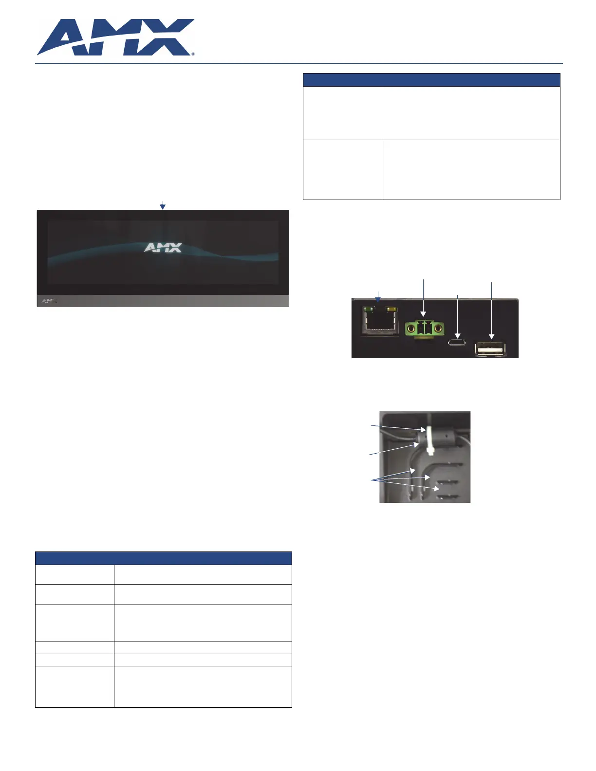
Panel Connectors and Wiring
FIG.2 shows the connectors located on the underside of the MXT-1901-PAN. The
Micro-USB port is used for camera video output. The underside USB port, as well as
the two rear USB ports, may be used with a flash drive for page transfers, firmware
upgrades, or Picture View. Any USB peripherals (mouse, keyboard, etc.) may be
connected to one of the two USB ports on the rear of the device.
The MXT-1901-PAN does not have individual channels on the base of the device to
allow passage of cables from underneath the base. Instead, it has one slot at the base
to allow options on cable configuration, with channels for securing power, Ethernet,
and Micro-USB cables (FIG.3).
Each channel side has slots for attaching tie-wraps to secure each cable. The ferrite
on the power cable must be secured with the included tie-wrap during installation to
prevent the possibility of the panel not sitting flush on the table.
Wiring Guidelines
The MXT-1901-PAN uses a 12 VDC-compliant power supply to provide power to the
panel via the 2-pin 3.5 mm captive wire PWR connector. Use the previously provided
power requirement information to determine the power draw. The incoming PWR and
GND wires from the power supply must be connected to the corresponding locations
within the PWR connector.
NOTE: Apply power to the panel only after installation is complete.
NOTE: Connecting power to the MXT-1901-PAN should be done using the included 2-
pin 3.5mm captive wire connector included with the device. This connector is retained
within its port with locking screws instead of the pins on each side of standard captive
wire connectors, and using force to insert a standard captive wire connector may
damage the device
.
FIG. 1 MXT-1901-PAN 19.4” Panoramic Tabletop Touch Panel
MXT-1901-PAN (FG5968-41) Specifications
Power Requirements:12VDC, 4.4A LPS: 2-pin, locking 3.5mm captive wire
connector.
Power Consumption:•Full-On: 35 W (12 VDC, 2.9 A)
•Standby: 7 W (12 VDC, 0.6 A)
Operating Environment:•Operating Temperature: 32° F to 104° F (0° C to 40° C)
•Storage Temperature: 4° F to 140° F (-20° C to 60° C)
•Humidity Operating: 20% to 85% RH
•Humidity Storage: 5% to 85% RH
Dimensions (HWD):
7" x 20 7/16” x 5 5/16” (177.8 mm x 519 mm x 134.6 mm)
Weight:
9.4 lbs (4.26 Kg)
Certifications:•UL
•FCC Part 15 Class B
•C-Tick CISPR 22 Class B
•CE EN 55022 Class B and EN 55024
•CB Scheme IEC 60950-1
Sleep Button
MXT-1901-PAN (FG5968-41) Specifications (Cont.)
Included Accessories: •MXT-1901-PAN Installation Guide (93-5968-041)
•MXA-CLK Modero X Series Cleaning Kit (FG5968-16)
•3.5mm Locking Captive Wire Connector (41-0002-SA)
•HPG-10 .75-inch HydraPort .75-IN. Grommet (FG570-01)
•Type A USB Covers (2)
•Tie Wrap for Power Source Ferrite
Other AMX Equipment:•PSN4.4 4.4AMP, 13.5VDCA5 Power Supply (FG423-45)
•MXA-USB-C USB Cover Kit (FG5968-18)
•MXA-MPL, Modero X Series Multi Preview Live
(FG5968-10)
•MXA-MP, Modero X Series Multi Preview (FG5968-20)
•MXA-STMK-19, Secure Table Mount Kit, 19.4" Modero X
Tabletop (FG5968-65)
FIG. 2 Rear connectors
FIG. 3 Tie-wrap for power connector ferrite
Ethernet 10/100
Port
Micro-USB
Port
USB Port
12 VDC
Power Port
Tie-wrap channels
Tie-wrap
Ferrite
Product specificaties
| Merk: | AMX |
| Categorie: | Monitor |
| Model: | MXT-1901-PAN |
| Kleur van het product: | Black, White |
| Beeldscherm: | IPS |
| Beeldschermdiagonaal: | 19.4 " |
| Resolutie: | 1920 x 530 Pixels |
| Touchscreen: | Ja |
| Grafische adapter: | G5 Graphics |
| Beeldscherm vorm: | Flat |
| Helderheid: | 350 cd/m² |
| Touch screen type: | Tafelblad |
| AMD FreeSync: | Nee |
| NVIDIA G-SYNC: | Nee |
| Type processor: | Quad Core |
| Ophangsysteem voor aan de muur: | Nee |
| Touchscreen technologie: | Capacitief |
Heb je hulp nodig?
Als je hulp nodig hebt met AMX MXT-1901-PAN stel dan hieronder een vraag en andere gebruikers zullen je antwoorden
Handleiding Monitor AMX

2 Februari 2024
14 November 2023
14 November 2023
14 November 2023
13 November 2023
13 November 2023
13 November 2023
13 November 2023
13 November 2023
13 November 2023
Handleiding Monitor
Nieuwste handleidingen voor Monitor
14 Mei 2026
14 Mei 2026
13 Mei 2026
13 Mei 2026
13 Mei 2026
12 Mei 2026
12 Mei 2026
12 Mei 2026
12 Mei 2026
12 Mei 2026