AMX MXA-FMK-07 Handleiding
AMX Niet gecategoriseerd MXA-FMK-07
Bekijk gratis de handleiding van AMX MXA-FMK-07 (2 pagina’s), behorend tot de categorie Niet gecategoriseerd. Deze gids werd als nuttig beoordeeld door 822 mensen en kreeg gemiddeld 4.7 sterren uit 6 reviews. Heb je een vraag over AMX MXA-FMK-07 of wil je andere gebruikers van dit product iets vragen? Stel een vraag
Pagina 1/2
QUICK START GUIDE
MXA-FMK-07 Modero X Series® Flush Mount Kit
MXA-FMK-07
The MXA-FMK-07 Flush Mount Kit (FG5968-71) mounts the Modero X Series 7” Wall
Mount Touch Panels flush with the wall. Once installed, simply press lightly on the black
border area on both sides of the touch panel, and the spring-loaded mechanism
switches the panel between the flush position or slightly extended from the wall
surface. The extended position gives access to the panel’s Sleep/Setup button, as well
as for enhanced speaker and microphone exposure. The MXA-FMK-07 is compatible
with all Modero X Series 7” Wall Mount Touch Panels, including:
•Refer to the 95-5968-71 diagram for detailed installation dimensions.
Installation of the Flush Mount Kit
The MXA-FMK-07 Flush Mount Kit (FIG. 1) is designed to attach the panel to most
standard wall and solid surface materials. It has two locking tabs (landscape: one on
top and one on bottom; portrait: one on each side) to help lock the Flush Mount Kit to
the wall. These locking tabs are only extended AFTER the Flush Mount Kit is inserted
into the wall. Using the locking tabs is highly recommended for standard mounting
surfaces such as walls.
WARNING: When installing the Flush Mount Kit, make sure that the assembly is in the
correct position and in the correct place. Once the locking tabs are extended and
locked into place, removing the Flush Mount Kit may be difficult without having
access to the back of the wall or causing damage to the wall.
Note: In order to guarantee a stable installation of the MXA-FMK-07, the thickness of the
wall material must be a minimum of .50 inches (1.27cm) and a maximum of .875 inches
(2.22cm). The surface should also be smooth and flat.
WARNING: The maximum recommended torque to screw in the locking tabs on the
plastic Flush Mount Kit is 5 IN-LB [56 N-CM]. Applying excessive torque while
tightening the tab screws, such as with powered screwdrivers, can strip out the
locking tabs or damage the plastic.
1.After ensuring proper placement, cut out the mounting surface, using the MXA-
FMK-07 Cutout Template (68-5968-06) as a guide (FIG. 2).
CAUTION: The cutout dimensions shown will allow the unit to pass through without any
dragging or interference. The outer phantom lines show the perimeter of the mounting
flange. If any part of the cutout extends up to or beyond that perimeter, the cut edge will
be visible after installation, or the unit could fall through the opening. A larger cutout
reduces the available surface to support the unit when mounted, so the cut should be as
close to the indicated dimensions as possible. If the cutout is too small, forcing the unit
into place could result in mechanical binding, faulty operation, or damage to the product.
Always check for a proper fit before final installation.
2.Remove the knockout at the top of the Flush Mount Kit (FIG. 3) and thread the
incoming wiring through the knockout hole. The MXA-FMK-07 has only one
knockout hole, at the top of the device (Landscape) or to the left (Portrait).
3.Thread the incoming Ethernet wiring from their terminal locations through the
surface opening and through the knockout.
4.Push the Flush Mount Kit flat into the mounting surface and secure with the
locking tabs (FIG. 4). In order to prevent damage to the touch panel, make sure
that any screws used are flush with the Flush Mount Kit, and the Flush Mount Kit
goes freely into the opening.
•MXD-701-P (FG5968-54)•MXD-700-P (FG5968-08)
•MXD-701-L (FG5968-55)•MXD-700-L (FG5968-14)
•MXD-700-P-NC (FG5968-28)•MXD-700-L-NC (FG5968-29)
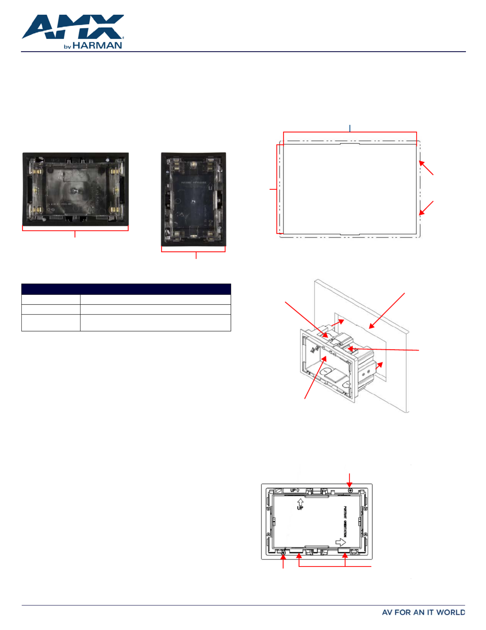
FIG. 1 MXA-FMK-07, LANDSCAPE AND PORTRAIT INSTALLATIONS
PRODUCT SPECIFICATIONS
Dimensions (HWD):5.50” x 8.01” x 3.48” (13.97 cm x 20.33 cm x 8.85 cm)
Weight:1.00 lbs (0.45 kg)
Included Accessories:•MXA-FMK-07 Quick Start Guide (93-5968-07)
•MXA-FMK-07 Cutout Template (68-5968-06)
Landscape Portrait
8.01” (20.33 cm)
5.50” (13.97 cm)
FIG. 2 MXA-FMK-07 CUTOUT TEMPLATE
FIG. 3 INSERTING THE MXA-FMK-07 INTO THE WALL SURFACE (LANDSCAPE)
FIG. 4 LOCKING TAB LOCATION ON THE MXA-FMK-07 (LANDSCAPE)
7.60”
5.09”
(12.94 cm)
(19.30 cm)
Perimeter
of Flush
Mount Kit
flange
Wall Surface
MXA-FMK-07
Knockout
Locking Tab
Note: The
MXA-FMK-07
has only one
knockout hole.
Locking Tab Screw
Locking Tab Screw
Use a screwdriver
or other flat tool
to hold the lower
edge of the back
box above the
case while snapping
down the touch panel.
Product specificaties
| Merk: | AMX |
| Categorie: | Niet gecategoriseerd |
| Model: | MXA-FMK-07 |
| Kleur van het product: | Zwart |
| Montagewijze: | Muur |
| Compatibiliteit: | MXD-701-P (FG5968-54), MXD-701-L (FG5968-55), MXD-700-P (FG5968-08), MXD-700-L (FG5968-14), MXD-700-P-NC (FG5968-28), MXD-700-L-NC (FG5968-29) |
| Aantal displays ondersteund: | 1 |
Heb je hulp nodig?
Als je hulp nodig hebt met AMX MXA-FMK-07 stel dan hieronder een vraag en andere gebruikers zullen je antwoorden
Handleiding Niet gecategoriseerd AMX

8 Juli 2026
7 Juli 2026
6 Juli 2026
10 Mei 2026
7 Mei 2026
5 Mei 2026
4 Mei 2026
24 November 2025
5 Augustus 2025
5 Augustus 2025
Handleiding Niet gecategoriseerd
Nieuwste handleidingen voor Niet gecategoriseerd
23 Juli 2026
23 Juli 2026
23 Juli 2026
23 Juli 2026
23 Juli 2026
22 Juli 2026
22 Juli 2026
22 Juli 2026
22 Juli 2026
22 Juli 2026