AMX MT-2002 Handleiding
AMX Niet gecategoriseerd MT-2002
Bekijk gratis de handleiding van AMX MT-2002 (2 pagina’s), behorend tot de categorie Niet gecategoriseerd. Deze gids werd als nuttig beoordeeld door 117 mensen en kreeg gemiddeld 4.2 sterren uit 2 reviews. Heb je een vraag over AMX MT-2002 of wil je andere gebruikers van dit product iets vragen? Stel een vraag
Pagina 1/2
AV FOR AN IT WORLD
®
QUICK START GUIDE
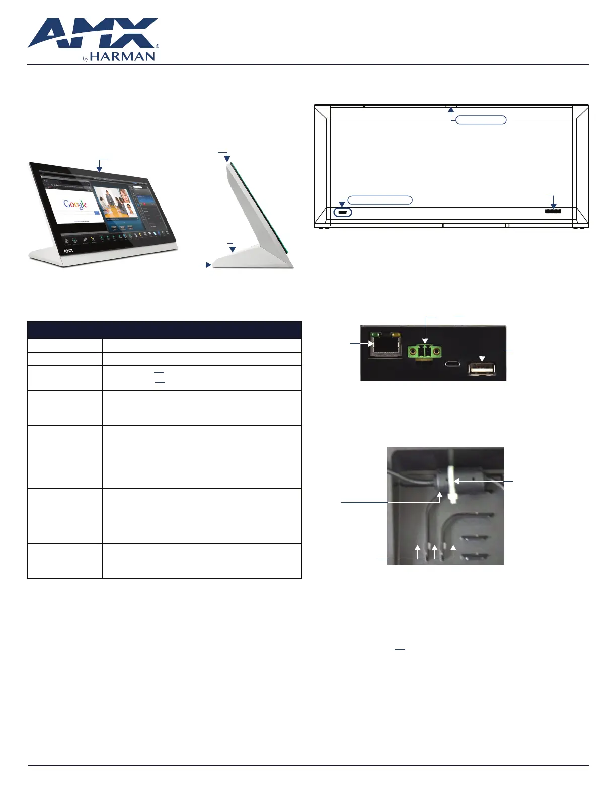
MT-2002 20.3” Modero G5 Panoramic Tabletop Touch Panel
Overview
The MT-2002 20.3” Modero G5 Panoramic Tabletop Touch Panel
(FG5969-35) features the G5 Graphics Engine to provide fast and smooth
animations and transitions, as well as a Quad Core Processor.
The MT-2002 features a panoramic capacitive multi-touch screen that
provides users access to multiple applications with minimal navigation. The
distinctive, low-prole design is engineered to sit perfectly on a table without
obstructing views.
Sleep button
Sleep button
USB Ports (2)
Cable slot
FIG. 1 MT-2002
Product Specifications
MT-2002 SPECIFICATIONS
Dimensions (HWD)9 3/16” x 20 3/8” x 5 7/8” (235 mm x 519 mm x 150 mm)
Weight12.3 lbs (5.58 Kg)
Power
Consumption
Full-On: 35 W (12V
..., 2.9A)
Standby: 7 W (12V
..., 0.58A)
External Power
Supply Required
Requires one of these AMX power sources (not included):
• PSR5.4 Power Supply, 12 VDC, 5.4A, 3.5mm Phoenix Connector with
Retention Screws (FG423-48)
• MXA-MPL Modero X/S Series Multi Preview Live (FG5968-10)
Certications• FCC Part 15 Class B
• AS/NZS CISPR 32 Class B
• CE EN 55032, 55035, 60950-1
• CB Scheme IEC 60950-1
• IC
• IEC/EN-60950
• UL 60950-1
• RoHS/WEEE compliant
Environmental• Temperature (Operating): 32°F to 104°F (0°C to 40°C)
• Temperature (Storage): 4°F to 140°F (-20°C to 60°C)
• Humidity (Operating): 20% to 85% RH
• Humidity (Storage): 5% to 85% RH
• Power (“Heat”) Dissipation:
On: 119.4 BTU/hr
Standby: 23.9 BTU/hr
Included
Accessories
• Locking 2-pin Phoenix connector (41-0002-SA)
• MXA-USB-C, USB Port Cover Kit (FG5968-18)
• HPG-10-10K, 3/4” Mini-Grommet (FG570-01)
• MXA-CLK, Modero X/S Series Cleaning Kit (FG5968-16)
Connector Locations
Two Type A USB ports are located on the rear right corner of the device (FIG. 2).
Type A USB Ports
Speaker
Sleep button
FIG. 2 MT-2002-REAR VIEW
USB peripherals (mouse, keyboard, etc.) may be connected to either of the two
USB ports on the rear of the device.
The power and Ethernet connectors, as well as an additional USB port are
located on the bottom of the device (FIG. 3).
The underside USB port, as well as the two rear USB ports, may be used with a
ash drive for page transfers or rmware upgrades.
Ethernet
10/100 Port
Type A USB Port
12V
...Power Port
FIG. 3 MT-2002 UNDERSIDE CONNECTORS
The MT-2002 does not have individual channels on the base of the device
to allow passage of cables from underneath the base. Instead, it has one slot at
the base to allow options on cable conguration, with channels for securing
power and Ethernet cables (FIG. 4).
Ferrite
Tie-wrap channels
Tie-wrap
FIG. 4 TIE-WRAP FOR POWER CONNECTOR FERRITE
Each channel side has slots for attaching tie-wraps to secure each cable. The
ferrite on the power cable must be secured with the included tie-wrap during
installation to prevent the possibility of the panel not sitting ush on the table.
Other cables may be secured with tie-wraps if desired, but this is not necessary.
Wiring Guidelines
The MT-2002 uses a 12V ...-compliant power supply to provide power to
the panel via the 2-pin 3.5 mm captive wire PWR connector.
The incoming PWR and GND wires from the power supply must be connected to
the corresponding locations within the PWR connector.
Note: Apply power to the panel only after installation is complete.
Note: Connecting power to the MT-2002 should be done using the included
2-pin 3.5mm captive wire connector included with the device. This connector
is retained within its port with locking screws instead of the pins on each side of
standard captive wire connectors, and using force to insert a standard captive
wire connector may damage the device.
Product specificaties
| Merk: | AMX |
| Categorie: | Niet gecategoriseerd |
| Model: | MT-2002 |
| Kleur van het product: | Grijs |
| Gewicht: | 5580 g |
| Breedte: | 519 mm |
| Diepte: | 150 mm |
| Hoogte: | 235 mm |
| RAM-capaciteit: | 2000 GB |
| Maximum resolutie: | 1920 x 800 Pixels |
| Aantal kleuren: | 16.7 M |
| Aantal USB 2.0-poorten: | 3 |
| Ethernet LAN, data-overdrachtsnelheden: | 10, 100 Mbit/s |
| Impedantie: | 4 Ohm |
| Temperatuur bij opslag: | -20 - 60 °C |
| Ondersteunde netwerkprotocollen: | CP, TCP, ICMP, ICSP, IGMP, DHCP, SSH, FTP, DNS, RFB (for VNC), HTTP |
| Luchtvochtigheid bij opslag: | 5 - 85 procent |
| Flash memory: | 16000 MB |
| Ethernet interface type: | Fast Ethernet |
| Stroomverbruik (typisch): | 35 W |
| Bedrijfstemperatuur (T-T): | 0 - 40 °C |
| Relatieve vochtigheid in bedrijf (V-V): | 20 - 85 procent |
Heb je hulp nodig?
Als je hulp nodig hebt met AMX MT-2002 stel dan hieronder een vraag en andere gebruikers zullen je antwoorden
Handleiding Niet gecategoriseerd AMX

10 Mei 2026
7 Mei 2026
5 Mei 2026
4 Mei 2026
24 November 2025
5 Augustus 2025
5 Augustus 2025
4 Augustus 2025
4 Augustus 2025
4 Augustus 2025
Handleiding Niet gecategoriseerd
Nieuwste handleidingen voor Niet gecategoriseerd
8 Juni 2026
8 Juni 2026
8 Juni 2026
8 Juni 2026
8 Juni 2026
8 Juni 2026
8 Juni 2026
8 Juni 2026
8 Juni 2026
8 Juni 2026