AMX MSA-AMK2-07 Handleiding
AMX Niet gecategoriseerd MSA-AMK2-07
Bekijk gratis de handleiding van AMX MSA-AMK2-07 (2 pagina’s), behorend tot de categorie Niet gecategoriseerd. Deze gids werd als nuttig beoordeeld door 573 mensen en kreeg gemiddeld 4.4 sterren uit 6 reviews. Heb je een vraag over AMX MSA-AMK2-07 of wil je andere gebruikers van dit product iets vragen? Stel een vraag
Pagina 1/2
QUICK START GUIDE
MSA-AMK/2-xx Any Mount Kits for Wall Mount
Modero S Series Touch Panels & AMX RoomBook Scheduling Panels
MSA-AMK/2 Any Mount Kits
The MSA-AMK/2-xx Any Mount Kits (FIG.1) are designed to mount Modero S Series
Wall Mount Touch Panels and AMX RoomBook Scheduling Panels (7” and 10.1”) into
standard sized single and double gang boxes in the US, EU, UK and Australia,
Models Available/Panel Compatibility
There are several versions of the Any Mount Kits available to accommodate 7” and 10”
Modero S Series (wall mount, landscape) and AMX RoomBook Scheduling Touch Panels:
“AMK2” Multi Mount Kits
The MSA-AMK2-10 and MSA-AMK2-07 Multi Mount Kits are intended for use with
second-generation “-L2” Modero S Series (Landscape/Wall Mount), as well as all AMX
RoomBook Scheduling touch panels.
Note that the installation procedure for the second-generation AMK2 versions of the
kits is essentially the same as the first-generation AMK kits, with only a minor change to
the top hook design.
Product Specifications
Installation of the Any Mount Kit
The Any Mount Kits are designed to utilize existing or newly installed gang boxes, with a
new back box to replace the back box included with the touch panel. To install an Any
Mount Kit and its accompanying touch panel:
1.Before starting the installation, ensure that Ethernet cable has been pulled to the
gang box, and that all appropriate Power Over Ethernet (PoE) injectors have been
connected to the cable going to the gang box.
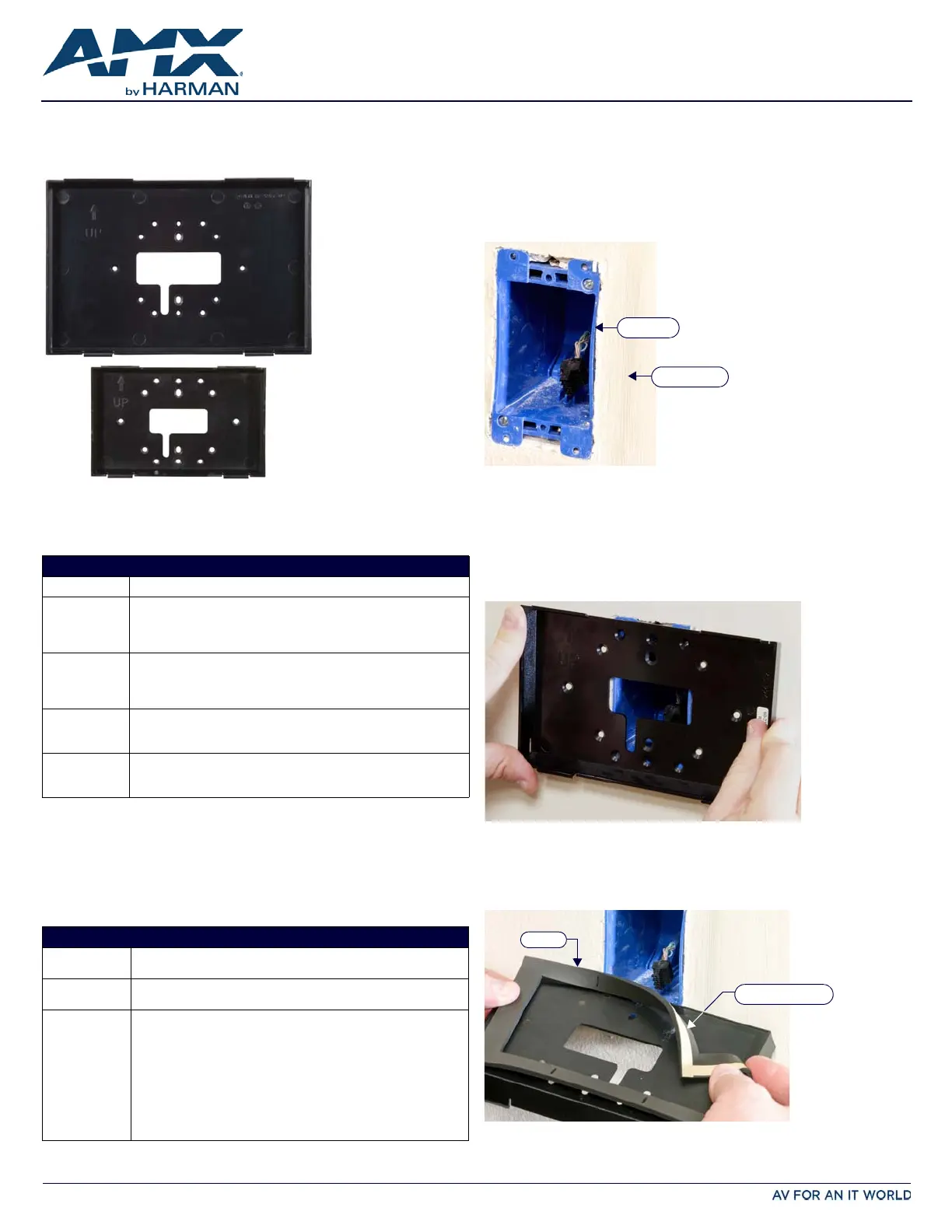
2.If the gang box already has an existing fixture or device installed in it, remove the
fixture or device to expose the gang box (FIG.2).
3.Pull the Ethernet cable into the gang box, making sure that the male RJ-45
connector is accessible within the gang box.
4.Match the screw connector holes on the gang box with the holes in the back box
(FIG.3).
•The Any Mount Kit back box has multiple holes to allow for single or double gang
box design, and for standard gang box designs from the US, UK, EU and Australia.
•Examine how the back box rests on the gang box - look for gaps between the back
box and the wall surface.
•If the gap between the wall and the back box is excessive, or if the installation of
the back box exposes too much of the gang box, you may apply the optional foam
gasket (MSA-AMK/2-07: 66-2265-29; MSA-AMK/2-10: 66-2265-30) to the back
of the back box. Peel the adhesive backing off the gasket and carefully apply it to
the back box surface (FIG.4).
FIG. 1
MSA-AMK/2-10 AND MSA-AMK/2-07
MODELS AVAILABLE/PANEL COMPATIBILITY:
Any Mount KitFor use with:
MSA-AMK2-10
(FG2265-36)
•MSD-1001-L2 (FG2265-31): 10.1" Modero S Series Landscape Wall
Mount Touch Panel
•RMBK-1001 (FG2265-40): 10.1” AMX RoomBook Scheduling Touch
Panel
MSA-AMK-10
(FG2265-26)
•MSD-1001-L (FG2265-01): 10.1" Modero S Series Landscape Wall
Mount Touch Panel
•RMBK-1001 (FG2265-40): 10.1” AMX RoomBook Scheduling Touch
Panel
MSA-AMK2-07
(FG2265-35)
•MSD-701-L2 (FG2265-32): 7" Modero S Series Landscape Wall Mount
Touch Panel
•RMBK-701 (FG2265-37): 7” AMX RoomBook Scheduling Touch Panel
MSA-AMK-07
(FG2265-25)
•MSD-701-L (FG2265-01): 7" Modero S Series Landscape Wall Mount
Touch Panel
•RMBK-701 (FG2265-37): 7” AMX RoomBook Scheduling Touch Panel
PRODUCT SPECIFICATIONS
Dimensions
(HWD):
•MSA-AMK/2-10: 6.53” x 9.76” x 0.98” (16.6cm x 24.8cm x 2.5cm)
•MSA-AMK/2-07: 4.88” x 7.38” x 0.91” (12.39cm x 18.75cm x 2.25cm)
Weight:•MSA-AMK/2-10: 0.25 lbs (113.40 g)
•MSA-AMK/2-07: 0.10 lbs (45.36 g)
Included
Accessories:
MSA-AMK/2-10:
•Back Box (60-2265-34)
•Gasket, Foam (66-2265-30)
•Screw, M3.5 X 30mm, PFH, Clear Zinc (4) (80-1620-04)
•Screw, #6-32 X 1.25, PFH, Type F, Clear Zinc (4) (80-1700-09)
MSA-AMK/2-07:
•Back Box (60-2265-33)
•Gasket, Foam (66-2265-29)
•Screw, M3.5 X 30mm, PFH, Clear Zinc (4) (80-1620-04)
•Screw, #6-32 X 1.25, PFH, Type F, Clear Zinc (4) (80-1700-09)
MSA-AMK-10
MSA-AMK-07
FIG. 2 EXISTING GANG BOX
FIG. 3 TESTING THE ALIGNMENT OF THE BACK BOX SCREW HOLES.
FIG. 4 APPLYING THE OPTIONAL FOAM GASKET TO THE BACK BOX.
Gang Box
Wall surface
Gasket
Adhesive backing
Product specificaties
| Merk: | AMX |
| Categorie: | Niet gecategoriseerd |
| Model: | MSA-AMK2-07 |
Heb je hulp nodig?
Als je hulp nodig hebt met AMX MSA-AMK2-07 stel dan hieronder een vraag en andere gebruikers zullen je antwoorden
Handleiding Niet gecategoriseerd AMX

10 Mei 2026
7 Mei 2026
5 Mei 2026
4 Mei 2026
24 November 2025
5 Augustus 2025
5 Augustus 2025
4 Augustus 2025
4 Augustus 2025
4 Augustus 2025
Handleiding Niet gecategoriseerd
Nieuwste handleidingen voor Niet gecategoriseerd
8 Juni 2026
8 Juni 2026
8 Juni 2026
8 Juni 2026
8 Juni 2026
8 Juni 2026
8 Juni 2026
8 Juni 2026
8 Juni 2026
8 Juni 2026