AMX DXF-TX-SMD Handleiding
AMX Niet gecategoriseerd DXF-TX-SMD
Bekijk gratis de handleiding van AMX DXF-TX-SMD (2 pagina’s), behorend tot de categorie Niet gecategoriseerd. Deze gids werd als nuttig beoordeeld door 165 mensen en kreeg gemiddeld 5.0 sterren uit 3 reviews. Heb je een vraag over AMX DXF-TX-SMD of wil je andere gebruikers van dit product iets vragen? Stel een vraag
Pagina 1/2
QUICK START GUIDE
DXLink™ Fiber Transmitters and Receivers
Overview
Applicable units for this guide include the DXF-TX-MMD, DXF-RX-MMD, DXF-TX-SMD,
DXF-RX-SMD, DXF-TX-MMS, DXF-RX-MMS, DXF-TX-SMS, and DXF-RX-SMS.*
All units support InstaGate Pro® and SmartScale® Technology.
* MM = multimode; SM = single mode; D at the end = Duplex; S at the end = Simplex.
Duplex units handle simultaneous-bidirectional or unidirectional data transfer; Simplex
units only handle unidirectional data transfer (multimode and single mode models
support different cable lengths).
The Multi-Format TXs and HDMI RXs transmit HDMI and audio over fiber optic cable
(Duplex models also transmit control data over fiber optic cable). The Multi-Format TXs
also have an input for analog video and an HDMI port on the front for local loop out.
All units can be set up in 1 of 3 ways (follow “Important” note below in all cases):
•Endpoint Mode (Switcher) – connect one or more units to an Enova DGX or Enova
DGX 100 Series Switcher with an integrated Master.
•Endpoint Mode (Standalone) – standalone TX/RX connected directly to each other
with one connected to NetLinx Central Controller via LAN or directly to Controller.
•Extender Mode (Standalone) – connect TX/RX pair directly to each other.
The Hardware Reference Manual – DXLink Fiber Transmitters and Receivers contains
complete documentation (including full specifications and supported input and output
resolutions); see the product page at www.amx.com
.
System Setup
IMPORTANT: For standalone pairs and for input/output boards with corresponding
TX/RX units, mix-or-match is allowed for Duplex and Simplex hardware (both types of
boards are also allowed in same enclosure). DXLink Fiber models must match: multimode
to multimode and single mode to single mode. If connecting Duplex and Simplex
products, see the “Hardware Reference Manual” for important information.
The TX and the RX work with a switcher that supports DXLink Fiber Technology for
transmission of HDMI (or with a Central Controller) or as a standalone pair. The TX
receives an HDMI signal (or analog video) and embedded audio from the source. Both
the video and embedded audio are transported over fiber optic cable to a DXLink Fiber
Input Board (or connector). The signal is routed via the DXLink Fiber Output Board (or
connector) to an RX. On TXs, stereo audio or digital audio connections are provided as
supplemental audio inputs. The RXs provide a stereo audio output. The TXs also have
an HDMI local out on the front. All Duplex TXs and RXs support USB, IR, RS-232 (for
serial data transfer) Ethernet. Simplex units only support Unidirectional Mode.
IMPORTANT: FIG. 6 shows duplex LC fiber cable; when using single LC fiber cables, be
sure to verify that the individual fiber from the transceiver’s TX label on one end of the
run are connected to the transceiver’s RX label on the other end and vice versa.
Mounting Options (Rack Trays and Mounting Brackets)
For details on the four versatile mounting kit options for V Style units (rack tray, rack
tray with fill plates, surface mount, and pole mount), see www.amx.com
.
IMPORTANT: When mounting under a surface, the units should be mounted upright and
lowered in the mounting bracket slots to provide an airflow gap between the surface and
the vent holes. If not using V Style brackets, be sure to leave a gap between the top of the
unit and the surface for heat to escape.
Fiber Optic Transceivers
The DXLink Fiber Transmitters and Receivers use SFP+ fiber optic transceivers. Fiber
optic transceivers are self-contained modules that send and receive optical signals over
fiber cable. DXLink SFP+ fiber optic transceivers are either multimode or single mode
and must be wired with the corresponding cable type. Both multimode and single mode
transceivers support bidirectional and unidirectional communication.
WARNING: DXLink Fiber units use laser transceivers, which are Class 1 Eye Safe per
IEC 60825-1/CDRH requirements. While the Class 1 category indicates that the
invisible laser used is safe, we recommend avoiding direct eye exposure when using
any optical fiber products (see OSHA directive referenced in the “Hardware
Reference Manual”).
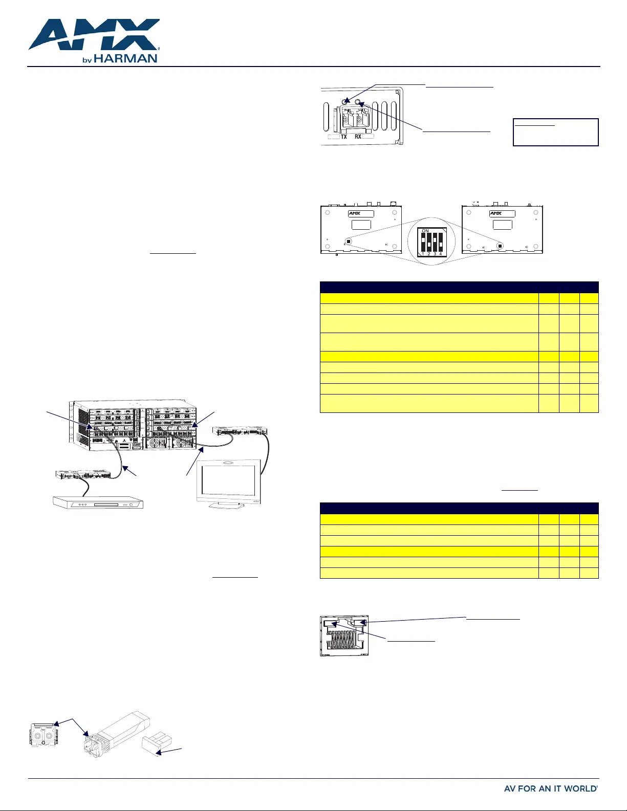
The following information applies to LEDs above fiber optic transceiver on Duplex units.
DIP Switch Toggles – Default OFF (for Auto-setup, see next page)
Before installing the units, find the scenario you are using in the applicable table below
and set the DIP switch toggles accordingly. Toggle #4 can be used for placing Duplex
units in Unidirectional Mode (for information, see the Hardware Reference Manual).
* Connection requires Duplex hardware with both fibers connected and in Bidirectional Mode (will not
work in Unidirectional Mode).
** Connect the ICS LAN port on one of the DXLink Fiber units to a network device (e.g., laptop).
*** Connect the ICS LAN 10/100 port on one of the DXLink Fiber units to the network device
(e.g., laptop) and connect the other unit to the network (the unit with Toggle #1 enabled).
^ With both units connected to boards in an Enova DGX Switcher (provides integrated NetLinx
control), connect the ICS LAN 10/100 port on one of the DXLink Fiber units to the network device
(e.g., laptop, IP controlled projector, AMX ICSLan EXB Device).
IMPORTANT:When connecting a TX or an RX in a standalone pair setup to a Master (or
Virtual Master) for upgrade purposes, Toggles #1 and #3 must be ON
. Toggle #2 is only
required on each unit if serial and/or IR control is required from the Master.
^^ Does not apply to DXLink Fiber, Simplex units: Toggle #4 can be set to ON or OFF.
ICS LAN 10/100 Port
The ICS LAN 10/100 port uses twisted pair cable. FIG. 5 shows the LEDs for this port.
Attaching Signal, Transport, and Control Cables
Important Cabling Requirements and Considerations:
•Fiber optic cable with LC termination for snap coupling with SFP+ transceivers
•LC Duplex conforming to ANSI TIA-EIA 604-10 (FOCIS 10A)
•DXLink Fiber multimode transceivers use OM3 50/125 μm multimode fiber optic
cable type over distances of up to 984 feet (300 m)^^^
•DXLink Fiber single mode transceivers use 9/125 μm single mode fiber optic cable
type over distances of up to 6.21 miles (10 km)^^^
•Do not create a network (Ethernet) loop. A network loop is created when the
enclosure and one or more of its DXLink Fiber units connect to a common LAN.
^^^ Cable quality is a determining factor for the maximum length of cable runs.
FIG. 1 DXLINK FIBER TX AND RX ENDPOINTS WITH COMPATIBLE DXLINK FIBER EQUIPMENT
FIG. 2 FIBER OPTIC TRANSCEIVER MARKED BLACK (MULTIMODE) OR BLUE (SINGLE MODE)
AC
DC
FLT
AC
DC
FLT
DXLink Fiber
DXLink Fiber RX
Enova DGX Switcher
Input Board
DXLink Fiber
Output Board
DXLink Fiber TX
Fiber optic cable
Destination
device
Source device
Latch and/or label color
Dust plug
SFP+ = enhanced small form-factor
pluggable fiber optic transceiver rated
at 10 Gbps transmission data rate.
FIG. 3 FIBER OPTIC TRANSCEIVER LEDS ON DUPLEX UNIT (SIMPLEX LEDS - SEE MANUAL)
FIG. 4 DIP SWITCH TOGGLES ENABLE/DISABLE SPECIAL FUNCTIONALITY
COMMON SCENARIOS - BIDIRECTIONAL, TOGGLE SETTINGS (#4 MUST BE OFF)
Standalone Setup (TX/RX Pair Direct Connection)*#1#2#3
AV signals only (plus serial/IR passthrough)OFFOFFOFF
AV with Ethernet passthrough to a network device** (plus serial/IR
passthrough)
ONOFFOFF
AV with NetLinx control of TX/RX unit and serial/IR ports, plus Ethernet
passthrough to a network device***
ONONON
TX/RX Connected to Enova DGX / DGX 100 Series (Switcher Setup)#1#2#3
AV signals onlyOFFOFFOFF
AV with Ethernet passthrough to a network device** ONOFFOFF
AV with NetLinx control of TX/RX unit and serial/IR portsOFFOFFON
AV with NetLinx control of TX/RX unit and serial/IR ports, plus Ethernet
passthrough to a network device^
ONOFFON
COMMON SCENARIOS - UNIDIRECTIONAL, TOGGLE SETTINGS (#4 MUST BE ON^^)
Standalone Setup (TX/RX Pair Direct Connection)#1#2#3
AV signals only (plus serial/IR passthrough)OFFOFFOFF
AV with NetLinx control of TX/RX unit and serial/IR portsONONON
TX/RX Connected to Enova DGX / DGX 100 Series (Switcher Setup)#1#2#3
AV signals onlyOFFOFFOFF
AV with NetLinx control of TX/RX unit and serial/IR portsONOFFOFF
FIG. 5 ICS LAN 10/100 (RJ-45) PORT
Video Status LED (left)
Link Status LED (right)
Simplex units - attach fiber
cable on side of transceiver
with illuminated LED.
Off - No video is present
On (solid) - HDCP video is present
Fast blink (mostly On) - unencrypted video is present
Slow blink (mostly Off) - free-run video is present
On - Link status is active
Off - Link status is not active
DIP switch
Transmitter
Receiver
Yellow LED (right)
On - Speed status is 100 Mbps
Off - Speed status is 10 Mbps
On - Link status is active
Off - Link status is not active
Green LED (left)
Product specificaties
| Merk: | AMX |
| Categorie: | Niet gecategoriseerd |
| Model: | DXF-TX-SMD |
Heb je hulp nodig?
Als je hulp nodig hebt met AMX DXF-TX-SMD stel dan hieronder een vraag en andere gebruikers zullen je antwoorden
Handleiding Niet gecategoriseerd AMX

10 Mei 2026
7 Mei 2026
5 Mei 2026
4 Mei 2026
24 November 2025
5 Augustus 2025
5 Augustus 2025
4 Augustus 2025
4 Augustus 2025
4 Augustus 2025
Handleiding Niet gecategoriseerd
Nieuwste handleidingen voor Niet gecategoriseerd
8 Juni 2026
8 Juni 2026
8 Juni 2026
8 Juni 2026
8 Juni 2026
8 Juni 2026
8 Juni 2026
8 Juni 2026
8 Juni 2026
8 Juni 2026